Low frequency amplifiers (LF) are used to convert weak signals, predominantly in the audio range, into more powerful signals acceptable for direct perception through electrodynamic or other sound emitters.
Note that high-frequency amplifiers up to frequencies of 10... 100 MHz are built according to similar circuits; the difference most often comes down to the fact that the capacitance values of the capacitors of such amplifiers decrease as many times as the frequency of the high-frequency signal exceeds the frequency of the low-frequency one.
A simple amplifier with one transistor
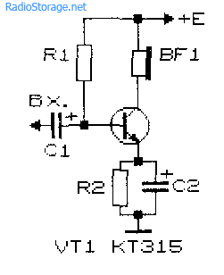
The simplest ULF, made according to a circuit with a common emitter, is shown in Fig. 1. A telephone capsule is used as a load. The permissible supply voltage for this amplifier is 3...12 V.
It is advisable to determine the value of the bias resistor R1 (tens of kOhms) experimentally, since its optimal value depends on the supply voltage of the amplifier, the resistance of the telephone capsule, and the transmission coefficient of a particular transistor.
Rice. 1. Circuit of a simple ULF on one transistor + capacitor and resistor.
To select the initial value of resistor R1, it should be taken into account that its value should be approximately one hundred or more times greater than the resistance included in the load circuit. To select a bias resistor, it is recommended to connect a constant resistor with a resistance of 20...30 kOhm and a variable resistor with a resistance of 100...1000 kOhm in series, after which, by applying a small amplitude audio signal to the input of the amplifier, for example, from a tape recorder or player, rotate the variable resistor knob to achieve the best signal quality at its highest volume.
The capacitance value of the transition capacitor C1 (Fig. 1) can range from 1 to 100 μF: the larger the value of this capacitance, the lower frequencies the ULF can amplify. To master the technique of amplifying low frequencies, it is recommended to experiment with the selection of element values and operating modes of amplifiers (Fig. 1 - 4).
Improved single-transistor amplifier options
More complicated and improved compared to the diagram in Fig. 1 amplifier circuits are shown in Fig. 2 and 3. In the diagram in Fig. 2, the amplification stage additionally contains a chain of frequency-dependent negative feedback (resistor R2 and capacitor C2), which improves the quality of the signal.
Rice. 2. Diagram of a single-transistor ULF with a chain of frequency-dependent negative feedback.

Rice. 3. Single-transistor amplifier with a divider to supply bias voltage to the base of the transistor.

Rice. 4. Single-transistor amplifier with automatic bias setting for the transistor base.
In the diagram in Fig. 3, the bias to the base of the transistor is set more “rigidly” using a divider, which improves the quality of operation of the amplifier when its operating conditions change. “Automatic” bias setting based on an amplifying transistor is used in the circuit in Fig. 4.
Two-stage transistor amplifier
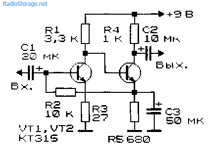
By connecting two simple amplification stages in series (Fig. 1), you can obtain a two-stage ULF (Fig. 5). The gain of such an amplifier is equal to the product of the gain factors of individual stages. However, it is not easy to obtain a large stable gain with a subsequent increase in the number of stages: the amplifier will most likely self-excite.

Rice. 5. Circuit of a simple two-stage low-frequency amplifier.
New developments of low-frequency amplifiers, the circuit diagrams of which are often presented on the pages of magazines in recent years, are aimed at achieving a minimum coefficient of nonlinear distortion, increasing output power, expanding the bandwidth of amplified frequencies, etc.
At the same time, when setting up various devices and conducting experiments, a simple ULF is often needed, which can be assembled in a few minutes. Such an amplifier must contain a minimum number of scarce elements and operate over a wide range of changes in supply voltage and load resistance.
ULF circuit based on field-effect and silicon transistors
The circuit of a simple low-frequency power amplifier with direct coupling between stages is shown in Fig. 6 [Rl 3/00-14]. The input impedance of the amplifier is determined by the rating of potentiometer R1 and can vary from hundreds of ohms to tens of megohms. You can connect a load with a resistance from 2...4 to 64 Ohms and higher to the amplifier output.
For high-resistance loads, the KT315 transistor can be used as VT2. The amplifier is operational in the range of supply voltages from 3 to 15 V, although its acceptable performance is maintained even when the supply voltage is reduced to 0.6 V.
The capacitance of capacitor C1 can be selected in the range from 1 to 100 μF. In the latter case (C1 = 100 μF), the ULF can operate in the frequency band from 50 Hz to 200 kHz and higher.
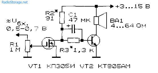
Rice. 6. Circuit of a simple low-frequency amplifier using two transistors.
The amplitude of the ULF input signal should not exceed 0.5...0.7 V. The output power of the amplifier can vary from tens of mW to units of W depending on the load resistance and the magnitude of the supply voltage.
Setting up the amplifier consists of selecting resistors R2 and R3. With their help, the voltage at the drain of transistor VT1 is set equal to 50...60% of the power source voltage. Transistor VT2 must be installed on a heat sink plate (radiator).
Track-cascade ULF with direct coupling
In Fig. Figure 7 shows a diagram of another seemingly simple ULF with direct connections between cascades. This kind of connection improves the frequency characteristics of the amplifier in the low-frequency region, and the circuit as a whole is simplified.

Rice. 7. Schematic diagram of a three-stage ULF with direct connection between stages.
At the same time, tuning the amplifier is complicated by the fact that each amplifier resistance has to be selected individually. Approximately the ratio of resistors R2 and R3, R3 and R4, R4 and R BF should be in the range (30...50) to 1. Resistor R1 should be 0.1...2 kOhm. Calculation of the amplifier shown in Fig. 7 can be found in the literature, for example, [R 9/70-60].
Cascade ULF circuits using bipolar transistors
In Fig. 8 and 9 show circuits of cascode ULFs using bipolar transistors. Such amplifiers have a fairly high gain Ku. Amplifier in Fig. 8 has Ku=5 in the frequency band from 30 Hz to 120 kHz [MK 2/86-15]. ULF according to the diagram in Fig. 9 with a harmonic coefficient of less than 1% has a gain of 100 [RL 3/99-10].

Rice. 8. Cascade ULF on two transistors with gain = 5.

Rice. 9. Cascade ULF on two transistors with gain = 100.
Economical ULF with three transistors
For portable electronic equipment, an important parameter is the efficiency of ULF. The diagram of such a ULF is shown in Fig. 10 [RL 3/00-14]. Here, a cascade connection of field-effect transistor VT1 and bipolar transistor VT3 is used, and transistor VT2 is connected in such a way that it stabilizes the operating point of VT1 and VT3.
As the input voltage increases, this transistor shunts the emitter-base junction of VT3 and reduces the value of the current flowing through transistors VT1 and VT3.

Rice. 10. Circuit of a simple economical low-frequency amplifier with three transistors.
As in the above circuit (see Fig. 6), the input resistance of this ULF can be set in the range from tens of ohms to tens of megohms. A telephone capsule, for example, TK-67 or TM-2V, was used as a load. The telephone capsule, connected using a plug, can simultaneously serve as a power switch for the circuit.
The ULF supply voltage ranges from 1.5 to 15 V, although the functionality of the device is maintained even when the supply voltage is reduced to 0.6 V. In the supply voltage range of 2... 15 V, the current consumed by the amplifier is described by the expression:
1(μA) = 52 + 13*(Upit)*(Upit),
where Upit is the supply voltage in Volts (V).
If you turn off transistor VT2, the current consumed by the device increases by an order of magnitude.
Two-stage ULF with direct coupling between stages
Examples of ULFs with direct connections and minimal selection of operating modes are the circuits shown in Fig. 11 - 14. They have high gain and good stability.

Rice. 11. Simple two-stage ULF for a microphone (low noise level, high gain).

Rice. 12. Two-stage low-frequency amplifier using KT315 transistors.
Rice. 13. Two-stage low-frequency amplifier using KT315 transistors - option 2.
The microphone amplifier (Fig. 11) is characterized by a low level of self-noise and a high gain [MK 5/83-XIV]. An electrodynamic type microphone was used as the VM1 microphone.
A telephone capsule can also act as a microphone. Stabilization of the operating point (initial bias at the base of the input transistor) of the amplifiers in Fig. 11 - 13 is carried out due to the voltage drop across the emitter resistance of the second amplification stage.

Rice. 14. Two-stage ULF with field-effect transistor.
The amplifier (Fig. 14), which has a high input resistance (about 1 MOhm), is made on a field-effect transistor VT1 (source follower) and a bipolar transistor - VT2 (with a common one).
A cascade low-frequency amplifier using field-effect transistors, which also has a high input impedance, is shown in Fig. 15.

Rice. 15. circuit of a simple two-stage ULF using two field-effect transistors.
ULF circuits for working with low-Ohm loads
Typical ULFs, designed to operate with low-impedance loads and having an output power of tens of mW and higher, are shown in Fig. 16, 17.

Rice. 16. A simple ULF for working with a low-resistance load.
Electrodynamic head BA1 can be connected to the output of the amplifier, as shown in Fig. 16, or diagonally to the bridge (Fig. 17). If the power source is made of two series-connected batteries (accumulators), the right output of the head BA1 according to the diagram can be connected to their midpoint directly, without capacitors SZ, C4.

Rice. 17. Circuit of a low-frequency amplifier with the inclusion of a low-resistance load in the diagonal of the bridge.
If you need a circuit for a simple tube ULF, then such an amplifier can be assembled even using one tube, look at our electronics website in the corresponding section.
Literature: Shustov M.A. Practical circuit design (Book 1), 2003.
Corrections in the publication: in Fig. 16 and 17, instead of diode D9, a chain of diodes is installed.
An audio frequency amplifier (AFA), or low frequency amplifier (LF) is one of the most common electronic devices. We all receive sound information using one or another type of ULF. Not everyone knows, but low-frequency amplifiers are also used in measurement technology, flaw detection, automation, telemechanics, analog computing and other areas of electronics.
Although, of course, the main use of ULF is to bring a sound signal to our ears using acoustic systems that convert electrical vibrations into acoustic ones. And the amplifier must do this as accurately as possible. Only in this case do we receive the pleasure that our favorite music, sounds and speech give us.
From the advent of Thomas Edison's phonograph in 1877 to the present, scientists and engineers have struggled to improve the basic parameters of the ULF: primarily for the reliability of the transmission of sound signals, as well as for consumer characteristics such as power consumption, size, ease of manufacture, configuration and use.
Beginning in the 1920s, a letter classification of classes of electronic amplifiers was formed, which is still used today. Classes of amplifiers differ in the operating modes of the active electronic devices used in them - vacuum tubes, transistors, etc. The main “single-letter” classes are A, B, C, D, E, F, G, H. Class designation letters can be combined in case of combining some modes. The classification is not a standard, so developers and manufacturers can use letters quite arbitrarily.
Class D occupies a special place in the classification. The active elements of the ULF output stage of class D operate in a switching (pulse) mode, unlike other classes, where the linear mode of operation of the active elements is mostly used.
One of the main advantages of Class D amplifiers is the coefficient of performance (efficiency) approaching 100%. This, in particular, leads to a reduction in the power dissipated by the active elements of the amplifier, and, as a consequence, to a reduction in the size of the amplifier due to the reduction in the size of the radiator. Such amplifiers place significantly lower demands on the quality of the power supply, which can be unipolar and pulsed. Another advantage can be considered the possibility of using digital signal processing methods and digital control of their functions in class D amplifiers - after all, it is digital technologies that prevail in modern electronics.
Taking into account all these trends, the Master Kit company offers wide selection of class amplifiersD, assembled on the same TPA3116D2 chip, but having different purposes and power. And so that buyers do not waste time searching for a suitable power source, we have prepared amplifier + power supply kits, optimally suited to each other.
In this review we will look at three such kits:
- (D-class LF amplifier 2x50W + power supply 24V / 100W / 4.5A);
- (D-class LF amplifier 2x100W + power supply 24V / 200W / 8.8A);
- (D-class LF amplifier 1x150W + power supply 24V / 200W / 8.8A).

First set Designed primarily for those who need minimal dimensions, stereo sound and a classic control scheme in two channels simultaneously: volume, low and high frequencies. It includes and.

The two-channel amplifier itself has unprecedentedly small dimensions: only 60 x 31 x 13 mm, not including control knobs. Dimensions of the power supply are 129 x 97 x 30 mm, weight – about 340 g.
Despite its small size, the amplifier delivers an honest 50 watts per channel into a 4 ohm load at a supply voltage of 21 volts!
The RC4508 chip, a dual specialized operational amplifier for audio signals, is used as a pre-amplifier. It allows the amplifier input to be perfectly matched to the signal source, and has extremely low nonlinear distortion and noise levels.

The input signal is supplied to a three-pin connector with a pin pitch of 2.54 mm, and power supply and speaker systems are connected using convenient screw connectors.

A small heatsink is installed on the TPA3116 chip using heat-conducting glue, the dissipation area of which is quite sufficient even at maximum power.
Please note that in order to save space and reduce the size of the amplifier, there is no protection against reverse polarity of the power supply connection (reversal), so be careful when supplying power to the amplifier.
Taking into account its small size and efficiency, the scope of application of the kit is very wide - from replacing an outdated or broken old amplifier to a very mobile sound reinforcement kit for dubbing an event or party.
An example of using such an amplifier is given.
There are no mounting holes on the board, but for this you can successfully use potentiometers that have fastenings for a nut.
Second set includes two TPA3116D2 chips, each of which is enabled in bridged mode and provides up to 100 watts of output power per channel, as well as with an output voltage of 24 volts and a power of 200 watts.

With the help of such a kit and two 100-watt speaker systems, you can sound a major event even outdoors!
The amplifier is equipped with a volume control with a switch. A powerful Schottky diode is installed on the board to protect against polarity reversal of the power supply.

The amplifier is equipped with effective low-pass filters, installed in accordance with the recommendations of the manufacturer of the TPA3116 chip, and together with it, ensuring high quality of the output signal.
The supply voltage and speaker systems are connected using screw connectors.

The input signal can be supplied either to a three-pin connector with a pitch of 2.54 mm, or using a standard 3.5 mm Jack audio connector.

The radiator provides sufficient cooling for both microcircuits and is pressed against their thermal pads with a screw located at the bottom of the printed circuit board.
For ease of use, the board also has a green LED indicating when the power is turned on.
The dimensions of the board, including capacitors and excluding the potentiometer knob, are 105 x 65 x 24 mm, the distances between the mounting holes are 98.6 and 58.8 mm. Dimensions of the power supply are 215 x 115 x 30 mm, weight about 660 g.
Third set represents l and with an output voltage of 24 volts and a power of 200 watts.

The amplifier provides up to 150 watts of output power into a 4 ohm load. The main application of this amplifier is to build a high-quality and energy-efficient subwoofer.
Compared to many other dedicated subwoofer amplifiers, the MP3116btl excels at driving large-diameter woofers. This is confirmed by customer reviews of the ULF in question. The sound is rich and bright.
The heatsink, which occupies most of the printed circuit board area, ensures efficient cooling of the TPA3116.

To match the input signal at the amplifier input, the NE5532 microcircuit is used - a two-channel low-noise specialized operational amplifier. It has minimal nonlinear distortion and wide bandwidth.
The input signal amplitude regulator with a slot for a screwdriver is also installed at the input. With its help, you can adjust the volume of the subwoofer to the volume of the main channels.

To protect against supply voltage reversal, a Schottky diode is installed on the board.
Power and speaker systems are connected using screw connectors.
The dimensions of the amplifier board are 73 x 77 x 16 mm, the distances between the mounting holes are 69.4 and 57.2 mm. Dimensions of the power supply are 215 x 115 x 30 mm, weight about 660 g.
All kits include MEAN WELL switching power supplies.

Founded in 1982, the company is the world's leading manufacturer of switching power supplies. Currently, MEAN WELL Corporation consists of five financially independent partner companies in Taiwan, China, the USA and Europe.
MEAN WELL products are characterized by high quality, low failure rates and long service life.
Switching power supplies, developed on a modern element base, meet the highest requirements for the quality of output DC voltage and differ from conventional linear sources in their light weight and high efficiency, as well as the presence of protection against overload and short circuit at the output.
The LRS-100-24 and LRS-200-24 power supplies used in the presented kits have an LED power indicator and a potentiometer for precise adjustment of the output voltage. Before connecting the amplifier, check the output voltage and, if necessary, set its level to 24 volts using a potentiometer.
The sources used use passive cooling, so they are completely silent.
It should be noted that all the amplifiers considered can be successfully used to design sound reproduction systems for cars, motorcycles and even bicycles. When powering amplifiers with a voltage of 12 volts, the output power will be slightly less, but the sound quality will not suffer, and the high efficiency allows you to effectively power the ULF from autonomous power sources.
We also draw your attention to the fact that all the devices discussed in this review can be purchased individually and as part of other kits on the website.
An audio frequency amplifier (AFA), or low frequency amplifier (LF) is one of the most common electronic devices. We all receive sound information using one or another type of ULF. Not everyone knows, but low-frequency amplifiers are also used in measurement technology, flaw detection, automation, telemechanics, analog computing and other areas of electronics.
Although, of course, the main use of ULF is to bring a sound signal to our ears using acoustic systems that convert electrical vibrations into acoustic ones. And the amplifier must do this as accurately as possible. Only in this case do we receive the pleasure that our favorite music, sounds and speech give us.
From the advent of Thomas Edison's phonograph in 1877 to the present day, scientists and engineers have been struggling to improve the basic parameters of the ULF: primarily for the reliability of the transmission of sound signals, as well as for consumer characteristics such as power consumption, size, ease of manufacture, configuration and use.
Beginning in the 1920s, a letter classification of classes of electronic amplifiers was formed, which is still used today. Classes of amplifiers differ in the operating modes of the active electronic devices used in them - vacuum tubes, transistors, etc. The main “single-letter” classes are A, B, C, D, E, F, G, H. Class designation letters can be combined in case of combining some modes. The classification is not a standard, so developers and manufacturers can use letters quite arbitrarily.
Class D occupies a special place in the classification. The active elements of the ULF output stage of class D operate in a switching (pulse) mode, unlike other classes, where the linear mode of operation of the active elements is mostly used.
One of the main advantages of Class D amplifiers is the coefficient of performance (efficiency) approaching 100%. This, in particular, leads to a reduction in the power dissipated by the active elements of the amplifier, and, as a consequence, to a reduction in the size of the amplifier due to the reduction in the size of the radiator. Such amplifiers place significantly lower demands on the quality of the power supply, which can be unipolar and pulsed. Another advantage can be considered the possibility of using digital signal processing methods and digital control of their functions in class D amplifiers - after all, it is digital technologies that prevail in modern electronics.
Taking into account all these trends, the Master Kit company offers Wide selection of Class D amplifiers, assembled on the same TPA3116D2 chip, but having different purposes and power. And so that buyers do not waste time searching for a suitable power source, we have prepared amplifier + power supply kits, optimally suited to each other.
In this review we will look at three such kits:
- MP3116mini + LRS-100-24 (D-class bass amplifier 2×50 W + power supply 24 V / 100 W / 4.5A);
- MP3116 + LRS-200-24 (D-class LF amplifier 2×100 W + power supply 24 V / 200 W / 8.8A);
- MP3116btl + LRS-200-24 (D-class LF amplifier 1×150 W + power supply 24 V / 200 W / 8.8A).

First set Designed primarily for those who need minimal dimensions, stereo sound and a classic control scheme in two channels simultaneously: volume, low and high frequencies. It includes the MP3116mini amplifier and LRS-100-24 power supply.

The two-channel amplifier itself has unprecedentedly small dimensions: only 60 × 31 × 13 mm, not including control knobs. Dimensions of the power supply are 129 × 97 × 30 mm, weight - about 340 g.
Despite its small size, the amplifier delivers an honest 50 watts per channel into a 4 ohm load at a supply voltage of 21 volts!
The RC4508 chip is used as a pre-amplifier - a dual specialized operational amplifier for audio signals. It allows the amplifier input to be perfectly matched to the signal source, and has extremely low nonlinear distortion and noise levels.

The input signal is supplied to a three-pin connector with a pin pitch of 2.54 mm, power supply and speaker systems are connected using convenient screw connectors.

A small heatsink is installed on the TPA3116 chip using heat-conducting glue, the dissipation area of which is quite sufficient even at maximum power.
Please note that in order to save space and reduce the size of the amplifier, there is no protection against reverse polarity of the power supply connection (reversal), so be careful when supplying power to the amplifier.
Taking into account its small size and efficiency, the scope of application of the kit is very wide - from replacing an outdated or broken old amplifier to a very mobile sound reinforcement kit for dubbing an event or party.
An example of using such an amplifier is given.
There are no mounting holes on the board, but for this you can successfully use potentiometers that have fastenings for a nut.
Second set includes the MP3116 stereo amplifier on two TPA3116D2 chips, each of which is connected in bridged mode and provides up to 100 watts of output power per channel, as well as with an output voltage of 24 volts and a power of 200 watts.

With the help of such a kit and two 100-watt speaker systems, you can sound a major event even outdoors!
The amplifier is equipped with a volume control with a switch. A powerful Schottky diode is installed on the board to protect against polarity reversal of the power supply.

The amplifier is equipped with effective low-pass filters, installed in accordance with the recommendations of the manufacturer of the TPA3116 chip, and together with it, ensuring high quality of the output signal.
The supply voltage and speaker systems are connected using screw connectors.

The input signal can be supplied either to a three-pin connector with a pitch of 2.54 mm, or using a standard 3.5 mm Jack audio connector.

The radiator provides sufficient cooling for both microcircuits and is pressed against their thermal pads with a screw located at the bottom of the printed circuit board.
For ease of use, the board also has a green LED indicating when the power is turned on.
The dimensions of the board, including capacitors and excluding the potentiometer knob, are 105 × 65 × 24 mm, the distances between the mounting holes are 98.6 and 58.8 mm. Dimensions of the power supply are 215 × 115 × 30 mm, weight about 660 g.
Third set is a single-channel MP3116btl low-frequency amplifier and an LRS-200-24 power supply with an output voltage of 24 volts and a power of 200 watts.

The amplifier provides up to 150 watts of output power into a 4 ohm load. The main application of this amplifier is to build a high-quality and energy-efficient subwoofer.
Compared to many other dedicated subwoofer amplifiers, the MP3116btl excels at driving large-diameter woofers. This is confirmed by customer reviews of the ULF in question. The sound is rich and bright.
The heatsink, which occupies most of the PCB area, ensures efficient cooling of the TPA3116.

To match the input signal at the amplifier input, the NE5532 microcircuit is used - a two-channel low-noise specialized operational amplifier. It has minimal nonlinear distortion and wide bandwidth.
The input signal amplitude regulator with a slot for a screwdriver is also installed at the input. With its help, you can adjust the volume of the subwoofer to the volume of the main channels.

To protect against supply voltage reversal, a Schottky diode is installed on the board.
Power and speaker systems are connected using screw connectors.
The dimensions of the amplifier board are 73 × 77 × 16 mm, the distances between the mounting holes are 69.4 and 57.2 mm. Dimensions of the power supply are 215 × 115 × 30 mm, weight about 660 g.
All kits include MEAN WELL switching power supplies.

Founded in 1982, the company is the world's leading manufacturer of switching power supplies. Currently, MEAN WELL Corporation consists of five financially independent partner companies in Taiwan, China, the USA and Europe.
MEAN WELL products are characterized by high quality, low failure rates and long service life.
Switching power supplies, developed on a modern element base, meet the highest requirements for the quality of output DC voltage and differ from conventional linear sources in their light weight and high efficiency, as well as the presence of protection against overload and short circuit at the output.
The LRS-100-24 and LRS-200-24 power supplies used in the presented kits have an LED power indicator and a potentiometer for precise adjustment of the output voltage. Before connecting the amplifier, check the output voltage and, if necessary, set its level to 24 volts using a potentiometer.
The sources used use passive cooling, so they are completely silent.
It should be noted that all the amplifiers considered can be successfully used to design sound reproduction systems for cars, motorcycles and even bicycles. When powering amplifiers with a voltage of 12 volts, the output power will be slightly less, but the sound quality will not suffer, and the high efficiency allows you to effectively power the ULF from autonomous power sources.
We also draw your attention to the fact that all the devices discussed in this review can be purchased individually and as part of other kits on the website
Other articles devoted to the construction of this ULF.
Schematic diagram of the power supply.

The power supply is assembled according to one of the standard schemes. Bipolar power supply is selected to power the final amplifiers. This allows the use of inexpensive, high-quality integrated amplifiers and eliminates a number of problems associated with supply voltage ripple and turn-on transients. https://site/
The power supply must provide power to three microcircuits and one LED. Two TDA2030 microcircuits are used as final power amplifiers, and one TDA1524A microcircuit is used as a volume control, network base and tone.
Electrical diagram of the power supply.

|
VD3... VD6 – KD226 |
C1 – 680mkFx25V C3... C6 – 1000mkFx25V |
A bipolar, full-wave rectifier with a midpoint is assembled using diodes VD3...VD6. This connection circuit reduces the voltage drop across the rectifier diodes by half compared to a conventional bridge rectifier, since in each half-cycle the current flows through only one diode.
Electrolytic capacitors C3...C6 are used as a rectified voltage filter.
The IC1 chip contains a voltage stabilizer to power the electronic volume, stereo and tone control circuits. The stabilizer is assembled according to a standard design.
The use of the LM317 chip is due only to the fact that it was available. Here you can use any integral stabilizer.
The protective diode VD2, indicated by a dotted line, is not necessary to use when the output voltage on the LM317 chip is below 25 Volts. But, if the input voltage of the microcircuit is 25 Volts or higher, and resistor R3 is a tuning resistor, then it is better to install a diode.
The value of resistor R3 determines the output voltage of the stabilizer. During prototyping, I soldered a trimmer resistor in its place, used it to set the voltage to about 9 Volts at the output of the stabilizer, and then measured the resistance of this trimmer so that I could install a constant resistor instead.
The rectifier feeding the stabilizer is made according to a simplified half-wave circuit, which is dictated by purely economic considerations. Four diodes and one capacitor are more expensive than one diode and one slightly larger capacitor.
The current consumed by the TDA1524A microcircuit is only 35mA, so this circuit is quite justified.
LED HL1 – amplifier power-on indicator. A ballast resistor for this indicator is installed on the power supply board - R1 with a nominal resistance of 500 Ohms. The LED current depends on the resistance of this resistor. I used a green LED rated at 20mA. When using a red LED type AL307 with a current of 5mA, the resistance of the resistor can be increased by 3-4 times.
Printed circuit board.

The printed circuit board (PCB) is designed based on the design of a specific amplifier and available electrical elements. The board has only one hole for mounting, located in the very center of the PCB, which is due to its unusual design.

To increase the cross-section of copper tracks and save ferric chloride, the areas free from tracks on the PP were filled using the “Polygon” tool.
Increasing the width of the tracks also prevents peeling of the foil from the fiberglass laminate in the event of a violation of the thermal regime or during repeated re-soldering of radio components.

According to the drawing given above, a printed circuit board was made from foil fiberglass with a cross section of 1 mm.
To connect the wires to the printed circuit board, copper pins (soldiers) were riveted into the holes of the board.
This movie requires Flash Player 9 |
||
And this is the already assembled printed circuit board of the power supply.
To see all six views, drag the picture with the cursor or use the arrow buttons located at the bottom of the picture.
The mesh on the PP copper tracks is the result of using this technology. 
When the board is assembled, it is advisable to test it before connecting the final amplifiers and the regulator unit. To test the power supply, you need to connect an equivalent load to its outputs, as in the diagram above.
Resistors of the PEV-10 type at 10-15 Ohms are suitable as a load for the +12.8 and -12.8 Volt rectifiers.
It’s a good idea to look at the voltage at the output of a stabilizer loaded onto a resistor with a resistance of 100-150 Ohms with an oscilloscope to ensure there is no ripple when the alternating input voltage decreases from 14.3 to 10 Volts.
P.S. Refinement of the printed circuit board.
During commissioning, the printed circuit board of the power supply was damaged.

During modification, we had to cut one track, item 1, and add one contact, item 2, to connect the transformer winding that powers the voltage stabilizer.
They are becoming a thing of the past, and now, in order to assemble any simple amplifier, you no longer have to struggle with calculations and rivet a large printed circuit board.
Now almost all cheap amplification equipment is made on microcircuits. The most widespread are TDA chips for amplifying audio signals. Currently used in car radios, powered subwoofers, home speakers and many other audio amplifiers, they look something like this:


Pros of TDA chips
- In order to assemble an amplifier on them, it is enough to supply power, connect speakers and several radio elements.
- The dimensions of these microcircuits are quite small, but they will need to be placed on a radiator, otherwise they will get very hot.
- They are sold at any radio store. There are some things on Ali that are a little expensive if you buy them at retail.
- They have built-in various protections and other options, such as muting the sound, etc. But according to my observations, the protections do not work very well, so microcircuits often die either from overheating or from. So it is advisable not to short-circuit the pins of the microcircuit with each other and not to overheat the microcircuit, squeezing all the juices out of it.
- Price. I wouldn't say they are very expensive. In terms of price and functions, they have no equal.
Single-channel amplifier on TDA7396
Let's build a simple single-channel amplifier using the TDA7396 chip. At the time of writing, I took it at a price of 240 rubles. The datasheet for the chip said that this chip can output up to 45 Watts into a 2 Ohm load. That is, if you measure the resistance of the speaker coil and it is about 2 ohms, then it is quite possible to get a peak power of 45 watts from the speaker.This power is quite enough to arrange a disco in the room not only for yourself, but also for your neighbors and at the same time get mediocre sound, which, of course, cannot be compared with hi-fi amplifiers.
Here is the pinout of the microcircuit:

We will assemble our amplifier according to a typical diagram, which was attached in the datasheet itself:

We apply +Vs to leg 8, and nothing to leg 4. Therefore, the diagram will look like this:

Vs is the supply voltage. It can be from 8 to 18 Volts. “IN+” and “IN-” – we send a weak sound signal here. We attach a speaker to the 5th and 7th legs. We set the sixth leg to minus.
Here is my wall mounted assembly

I did not use capacitors at the power input of 100nF and 1000uF, since I already have pure voltage coming from the power supply.
I rocked the speaker with the following parameters:

As you can see, the coil resistance is 4 ohms. The frequency band indicates that it is a subwoofer type.
And this is what my sub in a self-made housing looks like:

I tried to take a video, but the sound on the video is very poor. But I can still say that the phone at medium power was already hammering so hard that my ears were turning, although the consumption of the entire circuit in working form was only about 10 watts (multiply 14.3 by 0.73). In this example, I took the voltage as in a car, that is, 14.4 Volts, which is well within our operating range from 8 to 18 Volts.

If you do not have a powerful power source, then you can assemble it according to this diagram.
Don't get hung up on this particular chip. These TDA chips, as I already said, there are many types. Some of them amplify the stereo signal and can output sound to 4 speakers at once, as is done in car radios. So don’t be lazy to scour the Internet and find a suitable TDA. After completing the assembly, let your neighbors check out your amplifier by turning the volume knob all the way to the balalaika and leaning the powerful speaker against the wall).
But in the article I assembled an amplifier using a TDA2030A chip

It turned out very well, since the TDA2030A has better characteristics than the TDA7396
For variety, I’ll also attach another diagram from a subscriber whose TDA 1557Q amplifier has been working properly for more than 10 years in a row:

Amplifiers on Aliexpress
I also found kit kits on Ali on TDA. For example, this stereo amplifier is 15 watts per channel and costs $1. This power is quite enough to hang out in your room listening to your favorite tracks.

You can buy it.
And here it's ready right away

And in general, there are a lot of these amplifier modules on Aliexpress. Click on this link and choose any amplifier you like.