Let's begin!
What will we collect from?
We need to choose the heart of our system. In my opinion, for such signaling there is nothing better than Arduino Uno. The main criterion is a sufficient number of “pins” and price.
Key Features of Arduino Uno
Microcontroller - ATmega328
Operating voltage - 5 V
Input voltage (recommended) - 7-12 V
Input voltage (limit) - 6-20 V
Digital Inputs/Outputs - 14 (6 of which can be used as PWM outputs)
Analog inputs - 6
Constant current through input/output - 40 mA
Constant current for output 3.3V - 50mA
Flash memory - 32 KB (ATmega328) of which 0.5 KB is used for the bootloader
RAM - 2 KB (ATmega328)
EEPROM - 1 KB (ATmega328)
Clock frequency - 16 MHz
Fits!
Now you need to select a GSM module, because our alarm system must be able to notify the car owner. So, you need to google it... Here, an excellent sensor - SIM800L, the size is simply wonderful.

I thought and ordered it from China. However, everything turned out to be not so rosy. The sensor simply refused to register the SIM card on the network. Everything possible was tried - the result was zero.
There were kind people who provided me with a cooler thing - Sim900 Shield. Now this is a serious thing. The Shield has both a microphone and headphone jack, making it a full-fledged phone.

Key Features of Sim900 Shield
4 operating frequency standards 850/ 900/ 1800/ 1900 MHz
GPRS multi-slot class 10/8
GPRS mobile station class B
Complies with GSM phase 2/2+
Class 4 (2 W @850/ 900 MHz)
Class 1 (1 W @ 1800/1900MHz)
Control using AT commands (GSM 07.07, 07.05 and SIMCOM extended AT commands)
Low power consumption: 1.5mA(sleep mode)
Operating temperature range: -40°C to +85°C
Fits!
Ok, but you need to take readings from some sensors in order to notify the owner. If the car is towed away, then the position of the car will obviously change in space. Let's take an accelerometer and a gyroscope. Great. Ok, now we are looking for a sensor.
I think that the GY-521 MPU6050 will definitely fit. It turned out that it also has a temperature sensor. We should use it too, there will be such a “killer feature”. Let's assume that the owner of the car parked it under his house and left. The temperature inside the car will change “smoothly”. What happens if an intruder tries to break into the car? For example, he will be able to open the door. The temperature in the car will begin to change rapidly as the air in the cabin begins to mix with the air environment. I think it will work.

Main Features of GY-521 MPU6050
3-axis gyroscope + 3-axis accelerometer GY-521 module on MPU-6050 chip. Allows you to determine the position and movement of an object in space, angular velocity during rotation. It also has a built-in temperature sensor. It is used in various copters and aircraft models; a motion capture system can also be assembled based on these sensors.
Chip - MPU-6050
Supply voltage - from 3.5V to 6V (DC);
Gyro Range - ±250 500 1000 2000°/s
Accelerometer range - ±2±4±8±16g
Communication interface - I2C
Size - 15x20 mm.
Weight - 5 g
Fits!
A vibration sensor will also come in handy. Suddenly they try to open the car with “brute force”, or in the parking lot another car hits your car. Let's take the vibration sensor SW-420 (adjustable).

Main characteristics of SW-420
Supply voltage - 3.3 - 5V
Output signal - digital High/Low (normally closed)
Sensor used - SW-420
The comparator used is LM393
Dimensions - 32x14 mm
Additionally - There is an adjustment resistor.
Fits!
Screw on the SD memory card module. We will also write a log file.

Main characteristics of the SD memory card module
The module allows you to store, read and write to an SD card the data required for the operation of a device based on a microcontroller. The use of the device is relevant when storing files from tens of megabytes to two gigabytes. The board contains an SD card container, a card power stabilizer, and a connector plug for interface and power lines. If you need to work with audio, video or other large-scale data, for example, to log events, sensor data or store web server information, then the SD memory card module for Arduino will make it possible to use an SD card for these purposes. Using the module, you can study the features of the SD card.
Supply voltage - 5 or 3.3 V
SD card memory capacity - up to 2 GB
Dimensions - 46 x 30 mm
Fits!
And let's add a servo drive; when the sensors are triggered, the servo drive with the video recorder will turn and shoot a video of the incident. Let's take the MG996R servo drive.

Main Features of MG996R Servo Drive
Stable and reliable protection from damage
- Metal drive
- Double row ball bearing
- Wire length 300 mm
- Dimensions 40x19x43mm
- Weight 55 g
- Rotation angle: 120 degrees.
- Operating speed: 0.17sec/60 degrees (4.8V no load)
- Operating speed: 0.13sec/60 degrees (6V no load)
- Starting torque: 9.4kg/cm at 4.8V power supply
- Starting torque: 11kg/cm at 6V power supply
- Operating voltage: 4.8 - 7.2V
- All drive parts are made of metal
Fits!
We collect
There are a huge number of articles on Google about connecting each sensor. And I have no desire to invent new bicycles, so I will leave links to simple and working options.Good afternoon Again, a multi-review of Chinese electronic components, as usual about a little bit of everything, I’ll try to keep it short, but will it work? So, meet GSM alarm system costing up to 700 ₽. Interesting? Please use “cut”!
Let's get started! Before you start, I recommend taking a look at this one, fewer components and greater autonomy. So, the “technical specifications”, the basic requirements for signaling:
1) Notify when sensors are triggered.
2) In the event of a power failure, some autonomy must be provided.
3) Alarm control via SMS and calls.
Due to the fact that the process of creating an alarm took several months and some sellers no longer sell the components that were purchased from them, links will be updated to products from other sellers who have the maximum or close to the maximum number of product sales and best price. The prices in the review are current as of the date it was written.
List of what you will need:
List of changes
GSM_03_12_2016-14-38.hex- fixed operation of the device with the M590 modem.
GSM_05_12_2016-13-45.hex- added memtest console command, optimizing RAM usage.
GSM_2016_12_06-15-43.hex- added output of command results to the console, memory optimization. Occupied: 49% SRAM.
GSM_2016_12_07-10-59.hex- now phone numbers are added and removed correctly. Busy: 49% SRAM, 74% Flash Memory.
GSM_2016_12_07-15-38.hex- added the ability to connect a motion sensor, connect to pin A0 (in in this case pin A0 is used as digital). Added SMS commands PIROn, PIROff. Busy: 48% SRAM, 76% Flash Memory.
GSM_2016_12_08-13-53.hex- Now, after successfully executing a command that does not send an SMS message in response, the device flashes the blue LED once. Now, after an incorrect execution of a command that does not send an SMS message in response, the device blinks the blue LED twice. Now, after initializing the device parameters, if the “quiet” mode is enabled (SendSms = 0), the device blinks the blue LED frequently for 2 seconds. Fixed a bug due to which the number was not always deleted from memory using the DeletePhone command. Busy: 48% SRAM, 78% Flash Memory.
GSM_2016_12_11-09-12.hex- Added console commands AddPhone and DeletePhone, the syntax is similar to SMS commands. Memory optimization. Busy: 43% SRAM, 79% Flash Memory.
GSM_2017_01_03-22-51.hex- Support has been implemented for similar I/O port expanders on the PCF8574 chip, for connecting additional 8 sensors, including reed switches. Automatic address search and automatic module configuration. The standard names of sensors and the logical level of their response are changed using the EditSensor command. The contents of the alarm SMS for the main sensor (pin D0) have been changed: “Alarm! Main sensor! and motion sensor (pin A0) “Alarm! PIR sensor! Added EditSensor and I2CScan commands. Busy: 66% SRAM, 92% Flash Memory.
GSM_2017_01_15-23-26.hex- Support for A6_Mini modem. Monitoring the presence of external power (pin D7). Added SMS commands WatchPowerOn, WatchPowerOff. Added console commands ListConfig, ListSensor. Now the EditSensor SMS command works correctly. The output of debugging information to the port monitor has been slightly reduced. Occupied: 66% SRAM, 95% Flash Memory.
GSM_2017_01_16-23-54.hex- Now in the response message to the SMS command “Info” the status of the motion sensor is also reported. Fixed a bug due to which empty reply SMS messages were sometimes sent. Now the device notifies not only about a shutdown, but also about the resumption of external power. All modems began to chatter less, and now the port monitor is a little cleaner. Occupied: 66% SRAM, 95% Flash Memory.
GSM_2017_02_04-20-23.hex- Fixed the “Watch the power on” error. Now, after disarming, the “alarm pin” is turned off. Now, after deleting a number, the correct information is displayed in the console. Possibly fixed a bug due to which empty reply SMS messages were sometimes sent. Busy: 66% SRAM, 90% Flash Memory.
GSM_2017_02_14-00-03.hex- Now SMS messages are sent by default, the SendSms parameter is again equal to 1. Now, when the contacts of the main reed sensor are closed (closing the door), the device blinks with a blue LED for 2 seconds, indicating normal operation of the sensor. Busy: 66% SRAM, 90% Flash Memory.
GSM_2017_03_01-23-37.hex- The WatchPowerOn command has been removed. Added console command WatchPowerOff, identical to the SMS command. Added WatchPowerOn1, WatchPowerOn2 commands. WatchPowerOn1 - external power monitoring is enabled if the alarm system is armed, WatchPowerOn2 - external power monitoring is always enabled. The function of arming and disarming by external devices is implemented; pins A1(D15) and A2(D16) are used for this. The alarm arms/disarms when it appears on pin A1(D15) high level+5V or at pin A2(D16) low level GND. Pin A1(D15) is pulled up to GND, pin A2(D16) is pulled up to +5V through 20 (10) kOhm resistors. Added GuardButtonOn and GuardButtonOff commands. Now, after arming, the red LED flashes until the integrity of the main reed switch circuit is checked. If the circuit is intact, the red LED lights up. Occupied: 66% SRAM, 95% Flash Memory.
GSM_2017_03_12-20-04.hex- Now the console has become even cleaner, but if the “TestOn” test mode is enabled, additional information is displayed in the console. The “Sent!” bug has been fixed; information about sending messages is now correctly displayed in the console. Fixed the "repeated false call" bug. Now the balance request should work correctly on all modems. Occupied: 67% SRAM, 95% Flash Memory.
GSM_2017_04_16-12-00.hex- Corrected. Now the Info and Money commands will always send a response SMS. The GuardButtonOn command has been replaced by the GuardButtonOn1 and GuardButtonOn2 commands. Occupied: 67% SRAM, 99% Flash Memory.
GSM_2017_04_21-09-43.hex - not recommended for use, only for testing purposes, thanks for identifying errors :) - Now the sendsms parameter does not affect the sending of SMS messages for power grid monitoring. Added SMS command DelayBeforeGuard responsible for the delay when arming, the value cannot exceed 255 seconds. Added SMS command DelayBeforeAlarm, which is responsible for delaying the sending of notifications and turning on the “alarm pin” when sensors are triggered; the value cannot exceed 255 seconds. ClearSMS commands have been removed, messages are now deleted automatically upon receipt. Occupied: 68% SRAM, 100% Flash Memory.
GSM_2017_04_22-20-42.hex- Multiple bugs fixed. ClearSMS commands are again present in the firmware. Memory optimization. Busy: 68% SRAM, 98% Flash Memory.
GSM_2017_04_23-17-50.hex- Now the balance request should work correctly on all modems. Arming and disarming with external devices now works correctly. SMS response messages from the Info command should not be empty. Memory optimization. Busy: 68% SRAM, 98% Flash Memory.
GSM_2017_04_24-13-22.hex- Now sending console commands to GSM module is performed only if test mode is enabled. Now there is no division between SMS commands and console commands; all existing commands can be transmitted both via SMS and via the console. A bug with the Info command may have been fixed. Memory optimization. Busy: 68% SRAM, 94% Flash Memory.
GSM_2017_04_25-20-54.hex- Fixed a bug where the ListConfig command changed the value of the last event. Now, when entering commands through the console, unnecessary SMS messages are not sent. A bug with the Info command may have been fixed. Memory optimization. Busy: 66% SRAM, 94% Flash Memory.
GSM_2017_04_30-12-57.hex- Temporarily enabled the output of additional information to the console when sending SMS messages and generating a response to the Info command. A bug with the Info command may have been fixed. Memory optimization. Busy: 66% SRAM, 92% Flash Memory.
GSM_2017_05_06-11-52.hex- Fixed with DelayBeforeAlarm function. Occupied: 66% SRAM, 93% Flash Memory.
GSM_2017_05_23-21-27.hex- The output of information to the console has been slightly changed. Added support for port expansion modules on PCF8574A with addresses from 0x38 to 0x3f inclusive. Fixed bug c. Now the device reboots automatically after the FullReset, ResetConfig, ResetPhone commands and if the MemTest command is successfully executed. Added WatchPowerTime command. It is now possible to set the time after which an SMS message will be sent indicating that the external power source is turned off. Busy: 67% SRAM, 94% Flash Memory.
GSM_2017_05_26-20-22.hex- Initialization of expansion board sensor memory has been fixed. The AddPhone command syntax has been changed. Added EditMainPhone command. The operating principle of the notification system has been changed; when the sensor is triggered, SMS messages will be sent first, after which voice calls will be made. Alarm SMS messages will be sent to phone numbers with the sign “S” (SMS). Voice calls will be made to numbers with the “R” (Ring) sign. Messages about turning off/on the external power source will be sent to phone numbers with the sign “P” (Power). Added RingTime command. It is now possible to set the duration of an alarming voice call; the parameter can have a value from 10 to 255 seconds. The RingOn/RingOff command now globally enables/disables voice call alerts. Added ResetSensor command. Occupied: 68% SRAM, 99% Flash Memory.
GSM_2017_06_02-17-43.hex- The “I” (Info) parameter has been added to the AddPhone and EditMainPhone commands, which is responsible for SMS notification about arming or disarming the device. Now after adding the main number, the device automatically reboots. Now you can enter identical numbers into the device’s memory. When adding the second and subsequent duplicate numbers, the attributes “M”, “S”, “P” and “I” will be automatically removed from them. These numbers will be used for repeated voice calls when the sensors are triggered. A bug with incorrect console output after executing the AddPhone command has been fixed; now information is not displayed automatically after adding a number. Added Reboot command. Occupied: 69% SRAM, 99% Flash Memory.
GSM_2017_06_11-00-07.hex- Now again, when the contacts of the main reed sensor are closed (closing the door), the device blinks with a blue LED for 2 seconds, indicating normal operation of the sensor, but it does not take into account whether the device is armed or disarmed. RingOn/RingOff commands have been removed. Now the device can be disarmed during an alarm call; now they are made in the background. Occupied: 69% SRAM, 99% Flash Memory.
GSM_2017_07_04-21-52.hex- Now the Pause command does not send a response SMS. The TestOn and TestOff commands have been removed. The Management attribute has been removed from all numbers. Occupied: 68% SRAM, 96% Flash Memory.
GSM_2017_07_24-12-02.hex- Added ReedSwitchOn/ReedSwitchOff commands for monitoring the main reed sensor, now it can be turned on/off in the same way as a motion sensor. Fixed a bug in the Info command. The TestOn and TestOff commands are again present in the firmware. Occupied: 68% SRAM, 96% Flash Memory.
GSM_2017_07_26-10-03.hex- Added ModemID command. Automatic detection of the modem is carried out only if the value of this parameter is 0. After setting the parameter value to 0, the device is automatically rebooted. Busy: 68% SRAM, 98% Flash Memory.
GSM_2017_08_03-22-03.hex- Now the alarm can control external devices. For control, analog output A3 is used (D17 - used as digital). The logical output level (+5V or GND) can be changed; after changing the level through the configuration command, the device will automatically reboot. The duration of the external device control signal can be changed. Added ExtDeviceLevelLow, ExtDeviceLevelHigh, ExtDeviceTime, Open commands. Some changes in the logic of control commands. Memory optimization. Occupied: 68% SRAM, 99% Flash Memory.
GSM_2017_08_10-12-17.hex- The commands SmsOn/SmsOff, ReedSwitchOn/ReedSwitchOff, PIROn/PIROff and everything connected with them have been removed. The DelayBeforeAlarm command has been replaced with extended commands. Changed the output of the Info command. The output of the ListConfig command to the console has been optimized. Now any digital sensors with high or low response levels, including reed switches, can be connected to pins D6 and A0. Pins D6 and A0 should be connected to ground (GND) through a resistance of 10 (20) kOhm. If the sensor is set to a low response level (enabled in reed switch mode), then the integrity of the circuit is checked. The logical triggering level at inputs D6 and A0 (+5V or GND) can be changed; after changing the logical level, the device will automatically reboot. For each of the sensors (main, second, PCF expansion board), when triggered, its own time can be set, after which a notification will be made (SMS and/or voice call). "PIR Sensor" has been renamed to "Second sensor". Fixed the operation of the expansion card, an error due to which the device always notified when sensors were triggered, regardless of whether the device was armed or not. Now you can select an operating mode in which the device can monitor the sensors of the expansion card both in the armed mode (GuardOn) and in the disabled mode (GuardOff). Added commands PCFForceOn/PCFForceOff, MainSensorLevelHigh/MainSensorLevelLow/MainSensorLevelOff, SecondSensorLevelHigh/SecondSensorLevelLow/SecondSensorLevelOff, MainDelayBeforeAlarm, SecondDelayBeforeAlarm, PCFDelayBeforeAlarm. Occupied: 68% SRAM, 99% Flash Memory.
*Subsequent firmware versions include changes from previous versions.
Arduino Nano v3 ports used
D4- output of an “alarm” pin; when the sensor is triggered, a high level signal is set on this pin
D5- inverse output of the “alarm” pin; when the sensor is triggered, a low level signal is set on this pin
D6- reed sensor. Starting from version GSM_2017_08_10-12-17.hex, any digital sensors with high or low response levels, including reed switches, can be connected to pin D6. Pin D6 should be pulled to ground (GND) through a resistance of 10 (20) kOhm.
D7- connected to a voltage divider from an external +5V power source. Upper arm 2.2 kOhm, lower arm 3.3 kOhm.
Voltage divider

D8- TX modem
D9- RX modem
D10- red LED
D11- blue LED
D12- green LED
Peripheral connection:
A0- Motion Sensor . Starting from version GSM_2017_08_10-12-17.hex, any digital sensors with a high or low response level, including reed switches, can be connected to pin A0. Pin A0 should be pulled to ground (GND) through a resistance of 10 (20) kOhm.
A1- Input for external control. The alarm arms/disarms when a high level of +5V appears at the input.
A2- Inverse input for external control. The alarm arms/disarms when a low GND level appears at the input.
A3- Configurable (+5V or GND) output for controlling external devices. When a control command is received, the value at this output changes depending on what was set for a set period of time.
A4- SDA I2C
A5- SLC I2C
, for connecting additional 8 sensors.
Control commands for hex firmware
Attention! Teams dedicated in bold can only be executed from the main number, as they are responsible for the device configuration. Other commands can be executed from numbers with the “Management” attribute.
SMS - control commands are not case sensitive:
AddPhone- Add a phone number. In total, no more than 9 numbers can be added + 1 main number, which is automatically saved in memory the first time you call the device after resetting it to factory settings using commands ResetPhone or FullReset. Those. whoever called the device first after resetting it to factory settings is the “master”, this number is entered into the first memory cell and cannot be changed or deleted via SMS. It is not possible to add two identical numbers.
Example command:
Command syntax:
AddPhone- team
: - delimiter
5 - write to the fifth memory cell
+71234567890 - phone number
Up to version GSM_2017_05_26-20-22.hex:
a - “Alarm” parameter - SMS messages will be sent to numbers with this parameter - messages about alarm activation and messages about arming or disarming.
Starting from version GSM_2017_05_26-20-22.hex:
m - “Management” parameter - alarm management is enabled
s - “SMS” parameter - an SMS message will be sent when the sensors are triggered
r - “Ring” parameter - a voice call will be made when the sensors are triggered
p - “Power” parameter - an SMS message will be sent when the external power is turned on/off
i - “Info” parameter - an SMS message will be sent when arming or disarming
If the parameters “m”, “s”, “r”, “p”, “i” are missing, the phone is stored in memory, but is not used in any way.
DeletePhone- Delete phone number.
Example command:
Command syntax:
DeletePhone - command
: - delimiter
+71234567891 - phone number
EditMainPhone- Change the parameters “s”, “r”, “p”, “i” of the main phone, this number is stored in the first memory cell.
Example command:
Command syntax:
EditMainPhone - command
: - delimiter
srpi - parameters
BalanceNum- Changing the balance request number and processing the length of the request response. Default value for Beeline: #100#L22.
Example command:
Command syntax:
BalanceNum - command
: - delimiter
#103# - balance request number
L24 - The length (len) of the forwarded response is 24 characters, we cut off spam from the balance request.
EditSensor- Change the name of the sensor and the logical response level. There can be no more than 8 additional sensors in total. After changing the parameters, the device must be rebooted.
Example command:
EditSensor:1+Datchik dvizheniya v koridore#h
Command syntax:
EditSensor - command
: - delimiter
1 - write to the first memory cell
+ - separator
Datchik dvizheniya v koridore - the name of the sensor, cannot exceed 36 characters, including spaces.
#h - Sign of a high logical level from the sensor, upon receipt of which an alarm will be triggered. If "#h" is missing, the alarm will be triggered when a low logic level is received from the sensor.
SleepTime- The time the alarm goes to sleep when receiving the SMS command “Pause” is indicated in minutes. Default value: 15, cannot be less than 1 or more than 60.
Example command:
Command syntax:
SleepTime - command
: - delimiter
20 - 20 minutes of “sleep”.
AlarmPinTime- The time for which the alarm/inverse pin is turned on/off is indicated in seconds. Default value: 60, cannot be less than 1 second and more than 43200 seconds (12 hours).
Example command:
Command syntax:
AlarmPinTime - command
: - delimiter
30 - 30 seconds to turn on/off the alarm pin.
DelayBeforeGuard- Time before arming the device, after receiving the corresponding command.
Example command:
Command syntax:
DelayBeforeGuard - command
: - delimiter
25 - 25 seconds before arming
DelayBeforeAlarm- The time after which an “alarm” SMS notification will be sent if the alarm has not been disarmed during this period of time. Replaced by extended commands starting from version GSM_2017_08_10-12-17.hex
Example command:
Command syntax:
DelayBeforeAlarm - command
: - delimiter
40 - 40 seconds before sending an “alarm” notification
WatchPowerTime- Time in minutes after which an SMS message will be sent indicating that the external power source is turned off. If external power is restored before the set time has elapsed, the message will not be sent.
Example command:
Command syntax:
WatchPowerTime - command
: - delimiter
5 - 5 minutes before sending SMS message
RingTime- Duration of an alarming voice call, the parameter can have a value from 10 to 255 seconds.
Example command:
Command syntax:
RingTime - command
: - delimiter
40 - 40 the call duration will be 40 seconds, after which the next subscriber will be called.
ModemID- Forced installation of the model of the modem being used. Possible values: 0 - modem auto-detection, 1 - M590, 2 - SIM800l, 3 - A6_Mini.
Example command:
Command syntax:
ModemID - command
: - delimiter
2 - Modem ID.
ExtDeviceTime- The number of seconds by which the signal level at the control output of the external device will change.
Example command:
Command syntax:
ExtDeviceTime- command
: - delimiter
5 - 5 seconds
ExtDeviceLevelLow- The external device connected to output A3 is controlled by a low signal level (GND). The output will default to a high level of +5V until a control command from an external device is received
ExtDeviceLevelHigh- An external device connected to output A3 is controlled by a high signal level (+5V). The output will default to GND low until an external device control command is received.
ResetSensor- reset port expander sensors
ResetConfig- reset settings to factory settings
ResetPhone- deleting all phone numbers from memory
FullReset- reset settings, delete all phone numbers from memory, restore the default value of the BalanceNum command.
RingOn- enable notification by calling the “main” number recorded in the first memory cell when the sensor is triggered. Removed starting from version GSM_2017_06_11-00-07.hex
RingOff- turn off the notification by ringing when the sensor is triggered. Removed starting from version GSM_2017_06_11-00-07.hex
SmsOn- enable SMS notification when the sensor is triggered. Removed starting from version GSM_2017_08_10-12-17.hex
SmsOff- turn off SMS notification when the sensor is triggered. Removed starting from version GSM_2017_08_10-12-17.hex
PIROn- enable motion sensor processing
PIROff- disable motion sensor processing
ReedSwitchOn- enable processing of the main reed sensor
ReedSwitchOff- turn off processing of the main reed sensor
WatchPowerOn- enable external power control, an SMS message about turning off the external power will be sent provided that the alarm system is armed. Removed starting from version GSM_2017_03_01-23-37.
WatchPowerOn1- enable external power control, an SMS message about turning off the external power will be sent provided that the alarm system is armed.
WatchPowerOn2- enable external power control, an SMS message about turning off the external power will be sent in any case
WatchPowerOff- turn off external power control
GuardButtonOn- alarm control by external devices or button is enabled. Removed starting from version GSM_2017_04_16-12-00.
GuardButtonOn1- function setting or removing protection by external devices or button is enabled
GuardButtonOn2- function only productions armed by external devices or the button is turned on; disarming is done by calling the device or using an SMS command.
GuardButtonOff- alarm control by external devices or button is disabled
PCForceOn- constant monitoring of a group of all expansion module sensors
PCForceOff- monitoring a group of all expansion module sensors only when the device is armed
MainSensorLevelHigh- an alarm notification will be sent when a high level signal (+5 V) appears at the input (D6) from the sensor
MainSensorLevelLow- an alarm notification will be sent when a low level signal (GND) appears at the input (D6) from the sensor
MainSensorLevelOff- sensor input processing (D6) is disabled
SecondSensorLevelHigh- an alarm notification will be sent when a high level signal (+5 V) appears at the input (A0) from the sensor
SecondSensorLevelLow- an alarm notification will be sent when a low level signal (GND) appears at the input (A0) from the sensor
SecondSensorLevelOff- processing of the sensor input (A0) is disabled
MainDelayBeforeAlarm- the time after which an “alarm” SMS notification will be sent when the main sensor (D6) is triggered, if the alarm has not been disarmed during this period of time. The syntax is the same as the DelayBeforeAlarm command.
SecondDelayBeforeAlarm- time after which an “alarm” SMS notification will be sent when an additional sensor (A0) is triggered, if the alarm has not been disarmed during this period of time. The syntax is the same as the DelayBeforeAlarm command.
PCFDelayBeforeAlarm- the time after which an “alarm” SMS notification will be sent when the expansion board sensors (PCF8574) are triggered, if the alarm has not been disarmed during this period of time. The syntax is the same as the DelayBeforeAlarm command.
GuardOn - arm
GuardOff - remove guard
Open - external device control command
Info - check the status, in response to this message an SMS will be sent with information about which number the security was turned on/off
Pause - pauses the system for the time set by the sleeptime command in minutes; the system does not respond to sensor triggers.
TestOn - test mode is turned on, the blue LED flashes.
TestOff - test mode is turned off.
LedOff - turns off the standby LED.
LedOn - turns on the standby LED.
Money - balance request.
ClearSms - Delete all sms from memory
Console commands (up to version GSM_2017_04_24-13-22.hex) - entered in the Arduino IDE port monitor:
AddPhone - similar to the AddPhone sms command
DeletePhone - similar to the DeletePhone sms command
EditSensor - similar to the EditSensor sms command
ListPhone - output to the port monitor a list of phones stored in memory
ResetConfig - similar to the ResetConfig sms command
ResetPhone - similar to the ResetPhone sms command
FullReset - similar to the FullReset sms command
ClearSms - similar to the ClearSms sms command
WatchPowerOn1 - similar to the WatchPowerOn1 sms command
WatchPowerOn2 - similar to the WatchPowerOn2 sms command
WatchPowerOff - similar to the WatchPowerOff sms command
GuardButtonOn - similar to the GuardButtonOn sms command. Removed starting from version GSM_2017_04_16-12-00
GuardButtonOn1 - similar to the GuardButtonOn1 sms command
GuardButtonOn2 - similar to the GuardButtonOn2 sms command
GuardButtonOff - similar to the GuardButtonOff sms command
Memtest - test of the device's non-volatile memory; all device settings will be reset, similar to the FullReset command.
I2CScan - search and initialize supported devices on the I2C bus.
ListConfig - displays the current device configuration to the port monitor.
ListSensor - output to the port monitor of the current sensor configuration.
UPD. When using a motion sensor, to avoid false positives during modem operation, it is necessary between pins GND And A0 Arduino put up resistance, thank you comrade
AllowPhone = (“70001234501”, “70001234502”, “70001234503”, “70001234504”, “70001234505”) - Numbers that are allowed to manage security.
AlarmPhone = (“70001234501”, “70001234502”) - Numbers for sending SMS notifications when the sensor is triggered and notifications about disarming or arming. The first number in the list will be called when the sensor is triggered if the RingOn command is executed; by default, this option is enabled. This is done because SMS messages may arrive with some delay, but the call should go through immediately.
If a call is received from an authorized number or an SMS message with the GuardOn/GuardOff command, then, depending on the current security status, an SMS message about arming or disarming will be sent to the numbers listed in the AlarmPhone array, and an SMS message will also be sent to the number from which the call came.
When the sensor is triggered SMS messages are sent to all numbers from the AlarmPhone array (list) and a voice call is made to the first number from this array.
Light indication:
The LED lights up red - it is armed.
LED lights up green- disarmed, enabled/disabled by SMS command LedOn/LedOff.
The LED constantly blinks blue - it signals that everything is in order with the Arduino, the board is not frozen, it is used exclusively for debugging, it is turned on/off by the TestOn/TestOff SMS command.
* The code contains the LedTest() function, it blinks with a blue LED, it is made only to monitor the Arduino, blinks - it means it’s working, does not blink - it’s frozen. Haven't hung up yet :)
Not relevant!
Connecting 2 or more sensors for open firmware (applies only to this firmware sketch_02_12_2016.ino)
To connect additional reed sensors, we use free digital pins D2, D3, D5 or D7. Connection diagram with additional sensor on D7. 
Necessary changes in firmware
... #define DoorPin 6 // Input number connected to the main sensor int8_t DoorState = 0; // Variable for storing the state of the main sensor int8_t DoorFlag = 1; // Variable for storing the state of the main sensor #define BackDoorPin 7 // Input number connected to the additional sensor int8_t BackDoorState = 0; // Variable for storing the state of the additional sensor int8_t BackDoorFlag = 1; // Variable to store the state of the additional sensor...
void setup() ( ... pinMode(DoorPin, INPUT); pinMode(BackDoorPin, INPUT); ...
... void Detect() ( // Read values from sensors DoorState = digitalRead(DoorPin); BackDoorState = digitalRead(BackDoorPin); // Processing the main sensor if (DoorState == LOW && DoorFlag == 0) ( DoorFlag = 1; delay(100); if (LedOn == 1) digitalWrite(GLed, LOW); if (DoorState == HIGH && DoorFlag == 1)( DoorFlag = 0; delay(100); ) //Processing additional sensor if (BackDoorState == LOW && BackDoorFlag == 0) ( BackDoorFlag = 1; delay(100); if (LedOn == 1) digitalWrite(GLed, LOW); Alarm(); ) if (BackDoorState == HIGH && BackDoorFlag == 1)( BackDoorFlag = 0; delay(100); ) ) ...
And one more thing:
1. It is better to use diodes rated for a current of 2 A, since the module carries a current of 1 A and we still need to power the Arduino and the modem with something. This instance uses 1N4007 diodes; if they fail, replace them with 2 A ones.
2. I used all resistors for the LED at 20 kOhm, so as not to illuminate the entire corridor at night.
3. I also placed a 20 kOhm resistor on the reed sensor between the GND pin and the D6 pin.
That's all for now. Thank you for your attention! :)
I'm planning to buy +204 Add to favorites I liked the review +112 +243 jeweler February 15, 2012 at 04:34 pmAlarm in the room on Arduino
- Lumber room *
Good afternoon.
I would like to present to your attention an alarm system for any premises - home, store, office, which, when unwanted intrusion is detected, sends an email and calls mobile phone.
The uniqueness of the alarm system - all alarm management is carried out through the website makridenkov.ru/signals, from any device, Android, iPhone. The hardware is homemade, based on Arduino, with a low cost of ~$45. The circuit and hardware program are open at the link. Easy to repeat yourself.
General scheme of alarm operation.
As can be seen from the figure, Arduino transmits all information from the sensors to the control site. On the site, depending on the state of “on” or “off” the alarm, a decision is made to raise the alarm or not.
The Arduino sends a “connectivity” signal every 20 seconds. This allows you to notify the owner of the premises about the situation if the attacker turned off the electricity or somehow disabled the alarm system, broke it, or used any means of radio interference “gsm jammers”. That. notification is completely independent of the state of the iron in the room.
funny
The alarm can be used as a baby monitor.Install the sensor above your baby’s bed and calmly visit the nearest store. If the baby wakes up and starts moving, your mobile phone will ring.
A schedule of movement around the premises is created on the alarm management website. That. We get a picture of which paths and places are popular. For what? For example, find out how often your store’s salespeople visit the smoking room. Or, just for fun, ask the question, what does your spouse visit more often - a place for cooking or a computer with the Internet? The movement schedule answers these questions.
Video demonstration of work
Implementation
It is quite easy to assemble the iron yourself. Cost about $45.In detail, where and what to buy, follow the link, current information.
Schematic diagram in the figure.
Total
I hope the alarm will help you feel peace of mind for your store and home.I also think it would be interesting and useful to assemble such a device yourself, as a start to creative activity on the wonderful, convenient and simple Arduino platform. Although, in my opinion, I would prefer to write programs for Arduino in Ruby rather than in SI.
I would like to demonstrate the data that the alarm system was able to collect.
My travel schedule.
Usually, it is clear from the moving schedule that one room in an apartment is enough when you live alone. However, today I moved around all the rooms, for some reason.
It’s a funny observation, you can see exactly what time you went to work. And use this data as a tool for self-improvement and punctuality.
P.S. Photos of the finished and working device.
This is the end of the story.
All the best.
Tags: circuit, alarm, gsm, arduino, homemade,
This project concerns the development and improvement of a system to prevent/control any attempts to infiltrate by thieves. The developed security device uses an embedded system (includes a hardware microcontroller using open source software and a GSM modem) based on GSM (Global System for Mobile Communications) technology.
A security device can be installed in the house. Interface sensor burglar alarm also connected to a controller-based security system.
When an attempt is made to penetrate, the system sends a warning message (for example, sms) to the owner's mobile phone or to any pre-configured mobile phone for further processing.

The security system consists of an Arduino Uno microcontroller and a standard SIM900A modem based on GSM/GPRS. The whole system can be powered by any 12V 2A power source/battery.
Below is a diagram of an Arduino-based security system.
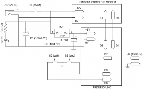
The operation of the system is very simple and does not require explanation. When power is supplied to the system, it goes into standby mode. When J2 connector pins are shorted, a pre-programmed warning message is sent to the required mobile number. You can connect any intrusion detector (such as a light guard or motion sensor) to the J2 input connector. Note that an active-low (L) signal on pin 1 of connector J2 will activate the burglar alarm.
Moreover, an optional “call-alarm” device has been added to the system. It activates a telephone call when the user presses the S2 button (or when another electronic unit initiates an alarm). After pressing the “call” button (S2), the call can be canceled by pressing another button S3 – the “end” button. This option can be used to generate a “missed call” alarm in case of intrusion.
The circuit is very flexible, so it can use any SIM900A modem (and, of course, the Arduino Uno board). Please read the modem documentation carefully before starting assembly. This will make the system manufacturing process easier and more enjoyable.
List of radioelements
| Designation | Type | Denomination | Quantity | Note | Shop | My notepad |
|---|---|---|---|---|---|---|
| Arduino board | Arduino Uno | 1 | To notepad | |||
| GSM/GPRS modem | SIM900A | 1 | To notepad | |||
| IC1 | Linear regulator | LM7805 | 1 | To notepad | ||
| C1 | 100uF 25V | 1 | To notepad | |||
| C2 | Electrolytic capacitor | 10uF 16V | 1 | To notepad | ||
| R1 | Resistor | 1 kOhm | 1 | To notepad | ||
| LED1 | Light-emitting diode | 1 | To notepad | |||
| S1 | Button | With fixation | 1 |
Its author wanted to do a homemade project so that it would be cheap and wireless.
This homemade product uses PIR sensor movement, and information is transmitted using an RF module.
The author wanted to use the infrared module, but since it has a limited range, plus it can work only line of sight with the receiver, so he chose an RF module with which he can achieve a range of approximately 100 meters.

To make it more convenient for visitors to view the alarm assembly, I decided to divide the article into 5 stages:
Stage 1: Creating a transmitter.
Stage 2: Create a receiver.
Stage 3: Software installation.
Stage 4: Testing of assembled modules.
Stage 5: Assembling the case and installing the module into it.
All the author needed was:
- 2 ARDUINO UNO/ARDUINO MINI/ARDUINO NANO boards for receiver and transmitter;
- RF transceiver module (433 MHZ);
- PIR motion sensor;
- 9V batteries (2 pieces) and connectors for them;
- Buzzer;
- Light-emitting diode;
- Resistor with a resistance of 220 Ohms;
- Bread board;
- Jumpers/wires/jumpers;
- Circuit board;
- Board-to-board pin connectors;
- Switches;
- Housings for receiver and transmitter;
- Colored paper;
- Mounting tape;
- Typesetting scalpel;
- Hot glue gun;
- Soldering iron;
- Wire cutters/insulation stripping tool;
- Metal scissors.

Stage 1.
Let's start creating the transmitter.
Below is a diagram of how the motion sensor works.

The transmitter itself consists of:
- Motion sensor;
- Arduino boards;
- Transmitter module.

The sensor itself has three outputs:
- VCC;
- GND;
- OUT.
After that, I checked the operation of the sensor


Attention!!!
Before downloading the firmware, the author makes sure that the current board and serial port are set correctly in the Arduino IDE settings. Then I uploaded the sketch:
Later, when the motion sensor detects movement in front of you, the LED will light up, and you will also be able to see a corresponding message on the monitor.

According to the diagram below.

The transmitter has 3 pins (VCC, GND, and Data), connect them:
- VCC > 5V output on the board;
- GND > GND ;
- Data > 12 pins on the board.
Stage 2.

The receiver itself consists of:
- RF receiver module;
- Arduino boards
- Buzzer (speaker).
Receiver Circuit:

The receiver, like the transmitter, has 3 pins (VCC, GND, and Data), connect them:
- VCC > 5V output on the board;
- GND > GND ;
- Data > 12 pins on the board.

Stage 3.
The author chose file libraries as the basis for the entire firmware. I downloaded it and placed it in the Arduino libraries folder.

Transmitter software.
Before uploading the firmware code to the board, the author set the following IDE parameters:
- Board -> Arduino Nano (or the board you are using);
- Serial Port ->

After setting the parameters, the author downloaded the Wireless_tx firmware file and uploaded it to the board:

Receiver software
The author repeats the same steps for the receiving board:
- Board -> Arduino UNO (or the board you are using);
- Serial Port -> COM XX (check the com port to which your board is connected).


After the author has set the parameters, he downloads the wireless_rx file and loads it into the board:

Afterwards, using a program that can be downloaded, the author generated a sound for the buzzer.
Stage 4.
Next, after downloading the software, the author decided to check if everything was working properly. The author connected the power supplies and passed his hand in front of the sensor, and the buzzer started working, which means everything is working as it should.

Stage 5.
Final assembly of the transmitter
First, the author cut off the protruding leads from the receiver, transmitter, arduino boards, etc.

After that, I connected the arduino board with the motion sensor and RF transmitter using jumpers.

Next, the author began making a housing for the transmitter.
First, he cut out a hole for the switch, as well as a round hole for the motion sensor, and then glued it to the body.


Then the author rolled up a sheet of colored paper and glued it to the front cover of the image in order to hide the internal parts of the homemade product.

After which, the author began to insert the electronic filling inside the case using double-sided tape.


Final assembly of the receiver
The author decided to connect the Arduino board to the circuit board with a rubber band, and we will also install an RF receiver.

Next, the author cuts two holes on the other case, one for the buzzer, the other for the switch.

And sticks it.