You need to be on top of things with electricity!!! (time-tested wisdom).
Many have probably heard that a real electrician is not one who is not afraid of electricity, but one who is able to avoid direct contact with electricity. According to statistics, electricians with ten or more years of experience most often die from electric shock. It is at this age that the sense of danger becomes dull. Some experienced electricians check the presence of electricity by touch, yes, by touch. But why risk your own life when there are instruments that indicate the presence of voltage?
There are quite a lot of devices that indicate the presence of voltage - from the simplest voltage indicator on a gas-discharge light bulb (neon) to devices that show not only the presence of voltage but also many other parameters.
In this article we will look at indicators and voltage indicators, which are most often used in their practice by both professional electricians and home craftsmen. In electrical installations, indicators with signal lamps are most often used.
Relatively recently, we have had voltage indicators that allow us to detect the presence of voltage without direct contact with a live conductor.
 An example of this type of device is a Chinese-made indicator (even though it says everywhere that it was made in Germany) - MS-18, MS-58, etc.
Such indicators consist of an LED, two miniature batteries and a pair of radio components. Such indicators can be used safely if you have enough experience and knowledge in electricity, since these indicators react to everything. For novice electricians and people without experience, using these probes is undesirable and even dangerous.
Single-pole voltage indicators can be made in-house. The figure shows data for the manufacture of a voltage indicator UNN-10. A cold cathode thyratron of the MTX-90 type, with an ignition threshold of 90 V, was used as a signal lamp.
If it is impossible to obtain a neon lamp or thyratron, it is allowed to use an incandescent lamp with a power of no more than 10 W, enclosed in one of the voltage indicator housings, as an indicator of the presence of voltage. A wire additional resistance is mounted in the second housing. For a 380 V network and a 220 V lamp with a power of 10 W, the value of the additional resistance should be 5000 Ohms.
The next most popular among electricians are bipolar voltage indicators. Such indicators consist of two parts. One of the parts contains the entire filling of the device, the second part contains the probe.
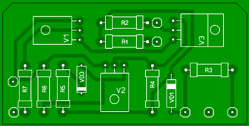
Two-pole voltage indicator: a - indicator UNN-10: b - indicator MIN-1, T - thyratron type MTX-90, R1 - shunt resistor type MLT-0.5, 1 MOhm, R2 - additional resistor type MLT-2, 0 ,24 MOhm, L - glow discharge lamp type IN-3: R - shunt resistor type BC, 10 MOhm, Rd - additional resistor type BC 3 MOhm.
Two-pole voltage indicator consists of a neon lamp, additional resistance and contacts 1. Neon lamp, so that there is no glow under the influence of capacitive current. The indicator elements are fixed in two plastic housings 2, connected by a flexible wire 3 1 m long with high-reliability insulation.
Bipolar indicators require touching two points of the electrical installation, between which it is necessary to determine the presence or absence of voltage.
There are quite a lot of varieties of such indicators. They also differ in functionality.
The simplest indicators only show the presence of voltage. An example of such an indicator is the PIN-90 series devices (-2m, -2mu), UN500, -453, UNNU-1, UNN-10, MIN-1, etc. More advanced models - the ELIN-1 series (-SZ, -S3 IPM, -S3 Combi) and many other devices show not only the presence of voltage in the test section of the circuit, but also its nominal value and voltage polarity.
The following indicators are used: neon lights, LEDs of various colors, digital indicators. There are also combined indicators, where along with light indication there is also sound, which makes working with devices more comfortable and safe.
Unlike single-pole pointers and indicators, in order to find out about the presence of voltage with these (double-pole) devices, it is necessary to use two probes. The use of such devices gives a more complete picture of the presence or absence of voltage, which is undoubtedly very important in the work of electricians.
In addition to checking for the presence or absence of voltage in the section of the circuit being tested, some bipolar indicators can be used as a “continuity test”, that is, to check the circuit for an open circuit.
 Digital devices are also quite popular among electricians. These universal devices allow you to check voltage, resistance, etc. The display uses a digital display, sound and light indication.
Some models are equipped without disturbing the conductor insulation. Also, many tester models are equipped with a temperature sensor, with which you can measure the temperature of equipment - transformers, motors, power switches.
Cautions:
1. It is not allowed to use it as a voltage indicator (a regular socket with two terminals) in networks with a linear voltage of more than 220 V, since if it is mistakenly switched to line voltage in a 380/220 V network, the lamp will explode and the fragments can injure the worker.
2. In practice, single-pole voltage indicators are often made on their own, usually in the form of a screwdriver. In this case, there are cases of improper manufacturing, and then there is a danger of electric shock. You cannot make the screwdriver shaft longer than 20 mm. If the rod is long, there is a danger of touching it when checking the voltage. It is advisable to tightly pull the insulating tube onto the rod, leaving an uninsulated section of no more than 5 mm in length. On the side close to the voltage source, there must be a thrust ring protruding 3-4 mm to prevent the hand from slipping.
Particular attention should be paid to the selection of a neon bulb so that the ignition threshold does not exceed 90 V. The IN-3 type lamp is most suitable. The additional resistance must be at least 200 kOhm.
The housing should be made of hard rubber or plastic of a dark color, in which it is easier to notice the glow of the light bulb. Manufactured signs must be tested.
In any case, using indicators and voltage indicators, knowledge and skills are required when working with them. Also, do not forget about safety precautions. And, trust the professionals, electricity, as you know, does not forgive jokes and mistakes!
In any modern home there is a huge number of different electronic devices, extension cords and power points for them. Often you have to check whether there is voltage in the outlet. A voltage indicator will help you with this, which most often is not at hand, but that’s not what we’re talking about.
Types of indicators
The simplest indicator is a simple screwdriver, inside of which it is located. Such a device can help you distinguish zero from phase. A two-pole indicator will be more advanced, although you can also take a single-line option.

The latter operates within 200 volts, but goes completely blind when the voltage level drops below 70 volts. It is capable of interacting only with open sections of wiring, sockets and other working areas of the circuit that are not hidden in any way.


Such a device cannot be used when working with networks under voltage of 380 volts. Also, it is not suitable for finding hidden contours. Make sure that there is no battery inside the indicator, otherwise it is better not to buy the device, since such models often show inaccurate readings.

Indicators for two working bands work on the same principle as the first option, only they have a higher range - they can work with networks up to four hundred volts. True, the wiring is of a hidden type and will not be revealed to him.

Single-band and double-band voltage indicators are most necessary for checking the phase in a particular wiring. They look at the order of wires in sockets, switches, and conductors.

Never, hear, never test wires for voltage with your hands or a spark contact. Also, do not connect a device with exposed wiring to a network of 220 volts or higher. Such manipulations can lead to injury, fire, short circuit, and even death. Electricity is no joke.

How to determine the phase
The question is very simple, however, many simply do not know the answer to it. If you have any voltage indicator, even the simplest one, after reading the instructions for it you can easily figure out what’s what. In the case of a simple indicator screwdriver, you just need to insert it into the socket and touch the contact - if the light comes on, you have found the phase, if not, you have determined zero.

For a screwdriver to work correctly, it must contain a resistor with a resistance of one megaohm. If the screwdriver is from the Middle Kingdom, this part of it will be made in the shape of a grayish cylinder.

Despite its simplicity, a screwdriver with a voltage indicator helps out in the simplest and most banal situations, and is especially indispensable in everyday life.


If you are working with a liquid crystal modification, you need to know that when checking the system voltage with a load below 50 volts, you need to touch a special touch panel.

If the voltage is much higher, but does not exceed 500 volts, then you should not touch the sensor. Such indicators do not have a special LED, therefore, to check the indicators, you need to bend over to it, and sometimes illuminate it with something.
Varieties
Most often, there are single-bar indicators of several types on store shelves. There are the simplest screwdrivers with an indicator inside, which is a simple neon light bulb, screwdrivers with additional batteries (usually batteries), and test screwdrivers that have several useful functions.

We have already talked a little about simple screwdrivers. Now let's look at their design in a little more detail. At the end there is a metal part called a probe. Inside there is a resistor, as previously mentioned, followed by a neon indicator, and all this is wrapped in a simple plastic case.

You already know how to use this type of voltage indicator. The range of their use is very limited, but it is more than enough for simple everyday tasks. They are as simple as possible, do not have additional batteries inside, and are particularly reliable.

Next are screwdrivers with indicators, inside of which there are batteries and additional LEDs. In terms of appearance, they are very similar to the first client. The only difference is that it is not necessary to touch the contact plate.

This screwdriver is good because it can find breaks in wiring. This is done very simply - take the indicator, apply the tip to one end of the wiring, take the other end with your hand, and then touch the sensor on the screwdriver. Personally, not so long ago such a screwdriver really helped me out. The wiring that goes from the outlet to the wall light needed to be replaced. Having gouged the wall, I pulled out the old wire and was about to install a new one, but I decided to check it again. It turned out that there were holes inside and the wire was shorting.


Agree, it would not be very pleasant to discover problems after everything has already been puttied again. This is not to mention the possible problems that such a wire could cause. Which voltage indicator you choose is up to you, but I am sure that this one will not be out of place in your tool case. They are a little more expensive than simple screwdrivers, but their price is still quite low.


Next up are modern screwdrivers with indicators. They differ in a certain abundance of possibilities and more sophisticated internals. According to the principle of operation, they are no different from the first two. They have a fairly high level of sensitivity, which allows them to detect wiring without contact, find the phase through a thin wire wrapper, and determine the voltage in the wire.
Sometimes, not always, but sometimes this is a very useful feature. The price tags for such screwdrivers are not at all steep, they work accurately, and in terms of use they are as simple as the first two options.

Where to use this? Again I will give an example from personal experience. Last year, the repair crew damaged the power cable for the TV and peripherals, which was thrown from the outlet and covered with a layer of plaster. The apartment is in an old building, so the wiring is not very well thought out, but I didn’t want to completely re-install it. Therefore, I made a branch that goes from the outlet and reaches the right place, and a power point is organized there. So it stopped working after cosmetic repairs.

The socket from which the branch comes was normal, so I thought about the wiring. I started drilling small holes in the wall and checking the cable, using a non-contact voltage indicator for this. I was ready to open the wall and get all two meters of cable. Through two holes I saw tension. It turned out that 20 centimeters from the new outlet, while installing the shelf, the would-be builders started making a hole in the wrong place and damaged the wire. For some reason they decided not to tell me about it, and they simply sealed the hole and hung the shelf higher. If it weren't for this screwdriver, a week after the repair, I would have started a new one again.

Two-line indicators
Two-way indicators consist of two parts in separate housings, which are connected by wire. These cases are made only from dielectric polymers, and the wire that connects them can reach one meter. Both parts are equipped with their own tip, an LED, or a gas light bulb, and a special resistor. In more expensive models there are also sound signals for various positions.


This is more of a niche tool, which is most often used by electricians and people whose work involves constant interaction with electrical appliances. Such an indicator can work with two contact groups or different equipment at once, and find the voltage and current between them. I think that you have already understood that the best voltage indicators for household use are the usual screwdrivers.

But two-band indicators have greater accuracy, more functions, and can determine the voltage in networks from 6 volts to 380 volts. That is why they are needed more by professionals who are engaged in complex work and installation of equipment with a high level of operating voltage.

In case you didn’t know, in everyday conditions, when the voltage level does not exceed one kilowatt, you can work without special equipment. If the network has a voltage of more than one kilowatt, it is necessary to use special dielectric gloves.

Two-line indicators also differ from each other. The cheapest options can do almost the same thing as screwdrivers. To determine the nominal voltage value and polarity on a separate segment, you will need to spend a lot of money. Such models are equipped with sound sensors, additional LEDs and emergency light sources if you suddenly need to work in a dark room.

Photo of voltage indicators


Checking the voltage in the circuit is a procedure necessary when performing various types of work related to electricity. Some amateur electricians, and sometimes professionals, use a homemade “control” for this - a socket with a light bulb to which wires are connected. Although this method is prohibited by the “Rules for the Safe Operation of Consumer Electrical Installations,” it is quite effective when used correctly. But still, for these purposes it is better to use LED identifiers - probes. You can buy them in a store, or you can make them yourself. In this article we will tell you what these devices are needed for, what principle they work on, and how to make an LED voltage indicator with your own hands.
What is a logic probe used for?
This device is successfully used when it is necessary to perform a preliminary check of the operability of the elements of a simple electrical circuit, as well as for the initial diagnosis of simple devices - that is, in cases where high measurement accuracy is not required. Using a logic probe you can:
- Determine the presence of a voltage of 12 - 400 V in the electrical circuit.
- Determine the poles in a DC circuit.

- Check the condition of transistors, diodes and other electrical elements.
- Determine the phase conductor in the AC electrical circuit.
- Ring the electrical circuit to check its integrity.
The simplest and most reliable devices with which the above manipulations are performed are an indicator screwdriver and a sonic screwdriver.
Electrician's probe: principle of operation and manufacture
A simple identifier with two LEDs and a neon light bulb, which has received the name “arcashka” among electricians, despite its simple device, allows you to effectively determine the presence of a phase, resistance in an electrical circuit, and also detect a short circuit (short circuit) in the circuit. The universal electrician's tester is mainly used for:
- Diagnostics for broken coils and relays.
- Continuity checks of motors and chokes.
- Checking rectifier diodes.
- Definitions of terminals on transformers with multiple windings.
This is not a complete list of tasks that can be solved using a probe. But the above is enough to understand how useful this device is in the work of an electrician.

A regular battery with a voltage of 9 V is used as a power source for this device. When the tester probes are closed, the current consumption does not exceed 110 mA. If the probes are open, then the device does not consume electricity, so it does not need either a diagnostic mode switch or a power switch.
The probe is capable of performing its full functions until the voltage at the power supply drops below 4 V. After this, it can be used as a voltage indicator in circuits.
During the continuity of electrical circuits, the resistance of which is 0 - 150 Ohms, two light-emitting diodes light up - yellow and red. If the resistance value is 151 Ohm - 50 kOhm, then only the yellow diode lights up. When a network voltage of 220 V to 380 V is applied to the probes of the device, the neon lamp begins to glow, and at the same time a slight flickering of the LED elements is observed.
The diagram of this voltage indicator is available on the Internet, as well as in specialized literature. When making such a probe with your own hands, its elements are installed inside the housing, which is made of insulating material.

Often, for these purposes, the housing from the charger of any mobile phone or tablet computer is used. A probe pin should be removed from the front part of the case, and a high-quality insulated cable, the end of which is equipped with a probe or an alligator clip, should be removed from the end part.
Assembling a simple voltage tester with an LED indicator is shown in the following video:
How to make an electrician's tester with your own hands?
Some thrifty hobbyists can find many useful things in their “arsenal,” including an earphone (capsule) for the TK-67-NT telephone.
Another similar device, equipped with a metal membrane, inside which there is a pair of series-connected coils, is also suitable.
Based on such a part, a simple sound probe can be assembled.
First of all, you need to disassemble the telephone capsule and disconnect the coils from each other. This is necessary in order to free their conclusions. The elements are placed in the earphone under the sound membrane, near the coils. After assembling the electrical circuit, we will receive a completely working identifier with sound indication, which can be used, for example, to check the tracks of printed circuits for mutual bridging.

The base of such a probe is an electric generator with an inductive opposite relationship, the main parts of which are a telephone and a low-power transistor (preferably germanium). If you do not have such a transistor, then you can use another one with N-P-N conductivity, but in this case the polarity of the power supply should be changed. If you cannot turn on the generator, the terminals of one (any) coil must be swapped with each other.
You can increase the sound volume by choosing the frequency of the electric generator so that it is as close as possible to the resonant frequency of the earphone. To do this, the membrane and the core must be placed at an appropriate distance, changing the interval between them until the desired result is obtained. Now you know how to make a voltage indicator based on a telephone earphone.
The manufacture and use of a simple voltage probe is clearly shown in the video:
Conclusion
In this material, we described how you can assemble an LED voltage indicator with your own hands, and also looked at the issue of making a simple diagnostic device based on an audio earphone.

As you can see, it is quite easy to assemble an LED indicator, as well as a sound detector, on your own - for this you just need to have a soldering iron and the necessary parts on hand, as well as have minimal electrical knowledge. If you don’t really like assembling electrical devices yourself, then when choosing a device for simple diagnostics, you should choose a regular indicator screwdriver, which is sold in stores.
The simplest work related to electricity is difficult to perform without measuring tools.
It is not at all necessary to measure the parameters of an electrical circuit with a tester; in many cases it is more convenient to use a universal probe that indicates the presence of these parameters through light signals. This is quite enough for convenient and safe work with electrical circuits.
The probe-indicator circuit under consideration does not contain batteries. Instead of the energy typically used in battery probes, it uses the energy of a charged capacitor.
Functionality.
The probe allows you to monitor the presence of alternating and direct voltage in the range from 24 to 220 V, carry out continuity testing of an electrical circuit with a resistance of up to 60 kOhm and determine the polarity in DC circuits.
When the XP1 and XP2 probes are connected to a direct current source in accordance with the input polarity, the green LED HL1 lights up, indicating not only the presence of direct voltage in the controlled circuit, but also the presence of a plus at the point of contact of the XP1 probe.
Changing the polarity on the probes to the opposite causes the red LED HL2 to light up, which, in addition to the presence of voltage, indicates contact with the plus of the HP2 probe.
When monitoring AC voltage, both LEDs light up simultaneously.
The continuity of the circuit during testing is indicated by the lighting of the red LED HL2.
This is the kind of information you can get with just two LEDs built into this simple indicator probe.
Probe design.
Radio components. To sell the device, you must purchase or find in your supplies the following parts:
Resistors R1-220 kOhm and R2-20 kOhm, power 2W, R3-6.8 kOhm;
LEDs HL1 – AL 307G, HL2 – AL 307B;
Diodes KD2 – VD5 – KD103 (possible replacement for KD 102);
Zener diode VD1 – KS222ZH (possible replacement for KS220ZH, KS522A);
Capacitor C1 - K50-6 1000x25.
Frame. Particular attention should be paid to the choice of housing - the convenience of working with the probe depends on its configuration and dimensions. Let's consider two housing options. The first option uses a relay cover, the second uses the body of an unknown gadget.

Holes are made in the housings for the output of the wire with the XP2 probe, LEDs are installed (only for the first option) and the XP1 probes are attached.
Pay. The dimensions of the case determine the geometry of the board. Installation can be hinged, but it is not difficult to do it on a printed circuit board. All radio components (except for LEDs in the first version) are mounted on a board that is mounted inside the case.


After installing the board into the case and soldering the conductors to the XP1 and XP2 probes, the probes and indicators are ready for use. The device does not need to be set up.
The charging time of the probe capacitor at a network voltage within 220-24V is 3-25 seconds. The capacitor discharge time when the probe probes are short-circuited is at least 2 minutes.

“CONTROL” and “DIALING” for ELECTRICIAN.
When checking the electrical circuit of a machine in noisy workshops, it is not entirely convenient to use measuring instruments; you have to simultaneously hold the probes of the device, look at its readings and also click the operating mode switch. And although the “RULES FOR SAFE OPERATION OF CONSUMER ELECTRICAL INSTALLATIONS” prohibit the use of test lamps, electricians often use a simple test lamp to check the serviceability of electrical circuits, which is used as a convenient and multifunctional “device.”
Although, in general, the point is not in the light bulb, but in the one who holds it - you can screw up both the voltage indicator and the certified device if it is in the hands of an irresponsible worker or someone who does not know how to handle it properly.
But the convenience of using the “control” correctly speaks for itself:
By the glow of the lamp, you can visually estimate the magnitude of the applied voltage;
The glow of an incandescent lamp is clearly visible in bright light;
Due to the low input resistance, it does not give false alarms from induced voltage (“crosstalk”) and “through the load”;
Allows you to check protective grounding circuits, the operation (or malfunction) of an RCD, and, among other things, can be used as a portable light source.
For safe use, the control lamp must be structurally enclosed in a case made of insulating material, transparent or with a slot for the passage of the light signal. Conductors must be flexible, reliably insulated, no more than 0.5 m long, to exclude the possibility of a short circuit when passing through a common input, exit the fittings into different holes, and have hard electrodes at the free ends, protected by insulated handles; the length of the bare end of the electrode should not exceed 10 - 20 mm.
To make a simple and easy-to-repeat version of the “control”: take two 220V 15W lamps for the refrigerator, solder them in series with each other, as conductors you can use multimeter probes with plastic holders at the ends, the wires in which it is advisable to replace with better ones. The flanges on these probes prevent the possibility of fingers getting into contact with the open ends of the probes and conductive parts of the installations. Then we place both lamps in a suitable case (for example, in a piece of transparent hose) and bring the wires out. 
In the process of checking the integrity of the wiring, you should strictly follow the electrical safety rules; the “control” should be suspended on the wires; when checking close to the floor, it should be moved as far away from you as possible.
TEST - INDICATOR.
In those cases (conditions) when it is more convenient to use a “control” rather than a device, that is, in simple diagrams for a preliminary assessment of the functioning of components during the repair and adjustment of electrical appliances and electronic devices, where measurement accuracy is not required. An indicator probe can often be useful to determine in the circuit being tested:
Availability of alternating or direct voltage from 12 to 400V,
Phase wire in alternating current circuits,
Approximate voltage value,
Polarity of DC circuits,
Perform continuity testing of circuits, including windings of electric motors, starters, transformers, contacts,
Check the serviceability of diodes, transistors, thyristors, etc.
These requirements are well met by various indicators with light and sound indications, which are simple and reliable in operation.
EASY TEST, equipped with two LEDs and a neon lamp, allows you to check the presence of a phase in the network, detect a short circuit and the presence of resistance in the circuit. With its help, you can check the coils of magnetic starters and relays for open circuits, ring the ends of chokes and motors, deal with the terminals of multi-winding transformers, check rectifier diodes and much more.
The probe is powered by a Krona battery or any other similar type with a voltage of 9V; the current consumption with the probes closed is no more than 110 mA; with the probes open, no energy is consumed, which allows you to do without a power switch and operating mode switch.
The functionality of the device is maintained when the supply voltage is reduced to 4V; when the battery is discharged (below 4V), it can work as an indicator of the mains voltage. 
When a circuit with a resistance of zero to 150 Ohms is tested, the red and yellow LEDs light up; with a circuit resistance of 150 Ohms to 50 kOhms, only the yellow LED lights up. When 220-380V mains voltage is applied to the probes, the neon lamp lights up and the LEDs flicker slightly.
The probe is made of three transistors; in the initial state, all transistors are closed, since the probe probes are open. When the probes are closed, a voltage of positive polarity is supplied through diode VD1 and resistor R5 to the gate of field-effect transistor V1, which opens and is connected through the base-emitter junction of transistor V3 to the negative wire of the power source. LED VD2 flashes. Transistor V3 also opens, LED VD4 lights up. When connected to resistance probes within the range of 150 Ohm-50 kOhm, the VD2 LED goes out, since it is shunted by resistor R2, the resistance of which is relatively less than that measured, and the voltage on it is not enough for it to glow. When mains voltage is applied to the probes, the neon lamp HL1 flashes.
A half-wave mains voltage rectifier is assembled using diode VD1. When the voltage on the zener diode VD3 (12V) is reached, transistor V2 opens and thereby closes field-effect transistor V1. LEDs flicker slightly.  DETAILS: Field-effect transistor TSF5N60M can be replaced with 2SK1365, 2SK1338 from pulse chargers of a video camera, etc. Transistors V2, V3 are replaceable with 13003A from an energy-saving lamp. Zener diode D814D, KS515A or similar with a stabilization voltage of 12-18V. Small-sized resistors 0.125 W. Neon lamp from a screwdriver indicator. Any LEDs, red or yellow. Any rectifier diode with a current of at least 0.3A and a reverse voltage of more than 600V, for example: 1N5399, KD281N.
When installed correctly, the probe begins to work immediately after power is applied. During setup, the range of 0-150 Ohms can be shifted in one direction or another by selecting resistor R2. The upper limit of the range 150 Ohm-50 kOhm depends on the instance of transistor V3.
The probe is placed in a suitable housing made of insulating material, such as the housing of a mobile phone charger. A probe pin comes out from the front, and a well-insulated wire with a pin (or crocodile) comes out from the end of the body.
UNIVERSAL INDICATOR ON THE CHIP.
Allows you to determine:
"Phase" wire in power circuits and electrical networks;
Availability of constant voltage in the range 10...120V;
Availability of alternating voltage in the range 10...240V;
Availability of signal in telephone networks;
Availability of a signal in the broadcast network;
Serviceability of fuses;
Serviceability of resistors with a resistance of 0... 100 kom;
Serviceability of capacitors with a capacity of 0.05...20 µF;
Serviceability of transitions of silicon diodes and transistors;
Availability of TTL and CMOS pulses up to 10 kHz.
In addition, you can find the ends of the wires in the wiring harness, both with the help of supply voltage and without it. 
Schematic diagram of the indicator.
When the probes are open, the voltage at pin 1 of element DD1.1 is determined by the voltage drop across the series-connected elements HL1, HL2, R3 and R4 is not enough to trigger trigger DD1.1. The multivibrator on DD1.1, DD1.2 does not work, the HL4 LED does not light up. In this mode, the current consumed from battery GB1 does not exceed 2...3 µA, which allows the indicator to do without a power switch.
In the “continuity” mode of the circuits, when the probes are closed, the input current of the circuit passes through resistors R1-R4, the voltage at pin 1 of element DD1.1 increases and triggers the multivibrator on elements DD1.1, DD1.2. From the multivibrator, pulses with an oscillation frequency of about 3 kHz are supplied to element DD1.3 - a buffer amplifier for the HL4 LED. In addition to the light indication of the operation of the multivibrator, the BF1 emitter also produces an audible alarm, which, to increase the signal amplitude, is connected between two inverters - DD1.4 and DD1.1.
Applying a constant voltage of 10... 120V to the input of the indicator causes the LEDs HL1, HL2 to glow, and with the polarity reversed to that indicated at the inputs, HL3. With increasing controlled voltage, the brightness of their glow, noticeable to the eye already at 10V, increases. When monitoring an alternating voltage indicator of 10... 120V with a frequency of 50 Hz, the glow of all LEDs HL1 -HL4 is visible, and by ear the presence of voltage with a frequency of 50 Hz is noticeable due to the characteristic tone modulation of 3 kHz. Moreover, auditory control appears to be more sensitive, since this modulation is already noticeable at voltages above 1.5V.
When a working oxide capacitor with a capacity of 20 μF is connected to the probes (in accordance with the polarity of the voltage on the probes), it is charged through the R1 - R4 circuit. In this case, the duration of the tone signal is proportional to the capacitance of the capacitor being tested - about 2 seconds per microfarad.
Checking the serviceability of semiconductor diodes and transistor junctions requires no explanation. True, the reverse current of the p-n junction of a diode or transistor of more than 2 μA can cause an audible alarm for any polarity of the semiconductor junction.
TTL and CMOS logical levels are displayed with inversion, i.e. a high level corresponds to the absence of lighting of the HL4 LED and a tone signal, and a low level corresponds to the inclusion of an LED and a tone signal.
The advantage of the indicator is that the test voltage on its probes, not exceeding 4.5V at a current of 3 µA, is safe even for field and microwave devices.
The use of two resistors R1 and R2 in the circuit increases the safety of working with the indicator; the values of these resistors (R1 and R2) are selected depending on the limit value supplied to the controlled voltage input. So, to control the input voltage up to 380V, with a current through the HL1-HL3 LEDs of about 10 mA, the resistance of resistors R1 and R2 should be increased to 20 kOhm!
When connecting to operating equipment, it must be taken into account that the internal resistance of the indicator is only 24 kOhm.
In the design, it is recommended to use HL2 - AL307A or similar LEDs with a red glow, and HL4 - with a red or yellow glow (for example, AL307D). HL1, HL3 - AL307G or similar green light. Resistors R1, R2 - MLT-2, the remaining resistors and capacitors - any small ones. 

BF1 - any piezoceramic emitter; three 1.5V alkaline “button” cells, used in calculators, key fobs, flashlights, etc., are used as the G1 battery.
The design and installation of elements largely depends on the housing used; it is possible to produce a particularly small-sized structure using a microcircuit and surface-mounted parts. 
Drawing of a possible board option.
The board is designed for installation of MLT resistors and capacitors KM-6 (C1) and K10-17. LEDs are placed in a convenient place for observation on the front side of the case.
It is advisable to make the positive terminal of the input circuit of the device in the form of a probe, and the negative terminal in the form of a flexible wire with an alligator clip at the end.
If the parts are in good working order, adjustment of the device is usually not required. Current consumption with open inputs should not be more than 4 µA. If, when connecting the battery, the HL4 indicator lights up even when the terminals are open, you should select LEDs HL1, HL2 with a higher threshold voltage or HL3 with a lower reverse current of the p-n junction. You can increase the volume of the sound alarm by selecting resistor R6 or capacitor C1, adjusting the generator frequency closer to the frequency most efficiently emitted by the BF1 converter.
THE FOLLOWING DIAGRAM allows you to evaluate the magnitude and sign of the voltage ("+","-","~") within several limits: 36V, >36V, >110V, >220V, 380V, and you can also ring electrical circuits, contacts and relay coils, starters, incandescent lamps, p-n junctions, LEDs, etc., i.e. almost everything that an electrician most often encounters in the course of his work (with the exception of current measurement).

In the diagram, switches SA1 and SA2 are shown in the unpressed state, i.e. in the voltmeter position, the voltage value can be judged by the number of lit LEDs in the VD3...VD6 line, and the VD1 and VD2 LEDs show the polarity; the approximate (recommended) location of the elements on the front panel and in the case is shown in the figure. Resistor R2 must be made of two or three identical resistors connected in series, with a total resistance of 27...30 kOhm. Pressed switch SA2 turns the probe into a classic dialer, i.e. battery plus light bulb. If you press both switches SA1 and SA2, you can test circuits in two resistance ranges: - the first range - from 1 MOhm and above to ~1.5 kOhm (VD15 is lit); - second range - from 1 kOhm to 0 (VD15 and VD16 are lit). Zener diodes can be used in small-sized imported ones. Batteries (type "316") last a year or more.
The probe can be supplemented with a “phase” indicator (HL2, R8, contact E1), which will be very useful when repairing lighting.
Housing options depend on the dimensions of the parts used. It is better to place the switches on different sides of the board, then there will be fewer errors when using it at first. The most common error is that, without making sure that there is no voltage in any circuit, the user presses the switches to test, and the HL1 lamp burns out, acting in this case as a fuse. Thus, when working on open circuits, you must be careful and attentive, as required by safety regulations.
ELECTRICANT'S TEST.
Before you start working with the probe, the diagram of which is shown in the following figure, you need to charge the storage capacitor C1. To do this, simply insert the probe probes into the power outlet for a few seconds.
At the same time, the LEDs LED2 - LED6 light up, indicating that the probe is working and there is voltage in the network - 220V. 

During operation, the lighting of the LEDs indicates the presence of the following voltages:
LED4 - 36V;
LED3 - 110V;
LED2 - 220V;
LED1 - 380V.
LED5 is used for dialing (about a minute of continuous illumination), and LED6 indicates voltage polarity (when measuring voltage in DC circuits).
You need to pay attention to the fact that this is still a probe, not a measuring device, so the threshold for turning on the LEDs is not very clear, but quite sufficient. For example, at a voltage of 127V, LED4 and LED3 light up, and LED2 and LED1 are extinguished. It may be necessary to select resistances R1, R2 and R5 during setup for a more accurate indication.
The main elements of the probe are mounted on a printed circuit board; to reduce the thickness of the housing, VD1 and C1 are placed outside the board in the main body, where the circuit and indicators are located, and resistors R1 and R2 are in the auxiliary probe. When using a D816V zener diode, capacitor C1 must be designed for an operating voltage of at least 35V. With a high-quality capacitor, the charge remains for more than a day. The capacitor capacity can be increased. Diodes in the circuit - any with a maximum voltage above 50V.
UNIVERSAL TEST-INDICATOR.
The proposed device, consisting of an LED voltage scale, a unit for monitoring the conductivity of electrical circuits ("continuities"), an alternating voltage indicator and a phase wire indicator, is a good assistant when, during the repair and installation of electrical wiring, it becomes necessary to check the network voltage, determine the phase and neutral wires, " Ring the circuits for breaks or short circuits. 
The LED scale is made on LEDs LED2-LED6 and resistors R2-R6, shunting the LEDs, and has five gradations of standard voltages. The operation of the scale is based on the lighting of a certain LED when the voltage drop across its shunt resistor is about 1.7V. Circuit VD3, LED7 serves to indicate alternating voltage on the probe probes, as well as the reverse polarity of direct voltage compared to that indicated in the diagram.
The conductivity control unit consists of a storage capacitor of a relatively large capacity C1, its charging circuit VD1, VD2 and the indication circuit R7, LED1. When the probes are connected to a voltage source for a few seconds, the capacitor is charged through the diode VD1 from the voltage dropping across the zener diode VD2. The probe is ready to test the circuits.
If you touch the working circuit with the probes, the capacitor discharge current will flow through it, resistor R1, LED1 and resistor R7. The LED will light up. As the capacitor discharges, the brightness of the LED will decrease. The phase wire indicator is assembled according to the relaxation generator circuit, touching the E1 sensor with your finger, and touching the phase wire with the “+” probe. The voltage rectified by diodes VD4, VD5 charges capacitor C2. When the voltage across it reaches a certain value, the neon lamp HL1 will flash. The capacitor is discharged through it, the process is repeated.
It is advisable to select LEDs - indicated in the diagram or their foreign analogues, for example, L-63IT according to similar parameters, and LED1 - according to maximum luminous efficiency at low current. Instead of the BZY97(10V) zener diode indicated in the diagram, you can use D814B or KS168. Capacitor C1 - K50-35 or its foreign equivalent. Resistors R2-R9 - MLT of appropriate power, R1 - PEV, S5-37 with a power of at least 8W (you can install six MLT-2 resistors connected in series with a resistance of 1.3 kOhm).

The design can be made in the form of two probes made of dielectric material, connected to each other by a flexible wire in double insulation, designed for a voltage of at least 380V. The main probe, on which the indicators are located, and the auxiliary probe, which contains resistor R1. Operation in all modes is carried out without any switching and without an internal battery. The probes have pointed tips with a diameter of 3 and a length of 20 mm.
If all parts are in working order and installed correctly, the probe can be used immediately. You may have to select resistor R7 in order to achieve clear lighting of LED1 (when connecting a resistor with a resistance of 300...400 Ohms between the probes). But its resistance should not be significantly reduced, since this will cause a rapid discharge of the storage capacitor. And to achieve clearly visible flashes of a neon lamp, it is enough to select resistor R8.
When it is often necessary to monitor the performance and repair various devices where constant and alternating voltages of different values (36v, 100v, 220v and 380v) are used, the proposed probe is very convenient, since there is no need to switch at different controlled voltages. A VARIANT of such a probe on two-color LEDs, which, in addition to “testing” the circuits, allows you to visually determine the type of direct or alternating voltage and approximately estimate its value in the range from 12 to 380V, is presented in the following figure. 
The circuit contains a scale of two-color LEDs LED1-LED5, a phase wire indicator on a neon lamp HL1 and a “continuity indicator” - an indicator of the conductivity of the electrical circuit.
To use the device as a “dialing”, you must first charge the storage capacitor C1. To do this, the input of the device is connected for 15...20 s to a 220V network or to a constant voltage source of 12V or more (plus to plug Xp1). During this time, capacitor C1 manages to charge through the diode VD2 to a voltage slightly less than 5V (it is limited by the zener diode VD1 ). Upon subsequent connection to the controlled circuit, if it is working properly, the capacitor will be discharged through it, resistor R7 and LED6, which will light up. If the test is carried out briefly, then charging the capacitor will be enough for several tests, after which the charging of the capacitor should be repeated. To indicate voltage, the device input - pin Xp1 and Xp2 (using a flexible insulated wire) is connected to the controlled points. Depending on the potential difference between these points, different current flows through resistors R1-R6 and the zener diode VD1. As the input voltage increases, the current also increases, which leads to an increase in the voltage across resistors R2-R6. LEDs LED1-LED5 light up alternately, signaling the value of the input voltage. The values of resistors R2-R6 are selected so that the LEDs light up at voltage:
LED1 - 12V or more,
LED2 - 36V or more,
LED3 - 127V or more,
LED4 - 220V or more,
LED5 - 380V or more.
Depending on the polarity of the input voltage, the color of the glow will be different. If pin Xp1 is plus relative to socket Xs1. The LEDs light up red, if negative - green. With variable input voltage, the glow color is yellow. It should be noted that with an alternating or negative input voltage, LED6 may also light up.
In the phase wire indicator mode in the network, any of the inputs (Xp1 or Xp2) is connected to the controlled circuit and touch the E1 sensor with your finger; if this circuit is connected to the phase wire, the neon indicator lamp lights up.
The circuit uses: fixed resistors R1 - PEV-10. the rest are MLT, S2-23. capacitor - K50-35 or imported, diode KD102B can be replaced with any diode from the 1N400x series, zener diode KS147A - with KS156A, instead of two-color LEDs, you can use two different colors of light, turning them on back-to-back, it is advisable to use LED6 LED with increased brightness .
It should be noted that LEDs of different glow colors have different forward voltage values, so their switching thresholds at different input voltage polarities will not be the same.
LED1-LED5 and neon lamp HL1 are placed in a row so that they are clearly visible. Probe Xp1 - a metal pin, pointed at the end, is placed at the end of the housing, Xp2 - an auxiliary probe in which resistor R1 is located, connected to the main body with a flexible wire with good insulation. As an E1 sensor, you can use a screw located on the device body.
CONTINUITY TEST - VOLTAGE INDICATOR.
A rather convenient device that can be used to check the integrity of lines and the presence of both direct and alternating voltage, which can provide useful assistance to an electrician in his work. The circuit is a direct current amplifier using transistors VT1, VT2 with base currents limited by resistors R1-R3. Capacitor C1 creates a negative feedback circuit for alternating current, eliminating false indications from external noise. Resistor R4 in the VT2 base circuit serves to set the required resistance measurement limit, R2 limits the current when the probe operates in AC and DC circuits. Diode VD1 rectifies alternating current. 

In the initial state, the transistors are closed and the HL1 LED does not light up, but if the probes of the device are connected together or connected to a working electrical circuit with a resistance of no more than 500 kOhm, the LED lights up. The brightness of its glow depends on the resistance of the circuit being tested - the higher it is, the lower the brightness.
When the probe is connected to an AC circuit, the positive half-waves open the transistors and the LED lights up. If the voltage is constant, the LED will light up when there is a “plus” of the source on the X2 probe.
The device can use silicon transistors of the KT312, KT315 series with any letter index, with a P21e value from 20 to 50. You can also use pnp transistors by changing the polarity of the diodes and the power supply. It is better to install a silicon diode VD1 KD503A or similar. LED type AL102, AL307 with ignition voltage 2-2.6V. Resistors MLT-0.125, MLT-0.25, MLT-0.5. Capacitor - K10-7V, K73 or any other small-sized one. The device is powered by two A332 elements.
It is better to configure the device on a temporary circuit board, excluding resistor R4 from the circuit. Connect a resistor with a resistance of about 500 kOhm to the probes to set the upper limit of resistance measurement, and the LED should light up. If this does not happen, the transistors need to be replaced with others with a higher coefficient h21e. After the LED lights up, select the value of R4 to achieve a minimum glow at the selected limit. If necessary, you can enter other resistance measurement limits into the device by changing them using a switch. Probe X2 is fixed to the body, and X1 is connected to the device with a stranded wire, the latter can be made from a collet pencil or used ready-made from an avometer.
ABOUT OPERATING THE DEVICE. The serviceability of diodes and transistors is checked by comparing the resistances of p-n junctions. The absence of a glow indicates a break in the transition, and if it is constant, the transition is broken. When a working capacitor is connected to the probe, the LED flashes and then goes off. Otherwise, when the capacitor is broken or has a large leak, the LED lights up constantly. Thus, it is possible to test capacitors with ratings of 4700 pF and higher, and the duration of the flashes depends on the measured capacitance - the larger it is, the longer the LED burns.
When checking electrical circuits, the LED will light up only in cases where they have a resistance of less than 500 kOhm. If this value is exceeded, the LED will not light up.
The presence of alternating voltage is determined by the glow of the LED. At constant voltage, the LED lights up only when there is a “plus” of the voltage source on probe X2.
The phase wire is determined as follows: probe XI is taken in the hand, and probe X2 is touched to the wire, and if the LED lights up, then this is the phase wire of the network. Unlike the indicator on the neon, there are no false positives from external interference.
Performing phasing is also not difficult. If the LED lights up when the probe touches current-carrying wires, it means that the probes are on different phases of the network, and if there is no light, they are on the same phase.
The insulation resistance of electrical appliances is checked in this way. One probe touches the wire, and the other touches the body of the electrical appliance. If the LED lights up, then the insulation resistance is below normal. The absence of a glow indicates that the device is working properly. 

A slightly modified version of the previous circuit, which works as follows: When dialing: if the probes are connected to each other, the green LED will light up (with these circuit ratings, circuits with a resistance of up to 200 kOhm “ring”).
If there is voltage in the circuit, both green and red LEDs light up together: the probe works as an indicator of constant voltage from 5V to 48V and alternating voltage up to 380V, the brightness of the red LED depends on the voltage in the circuit being tested, i.e. at 220V the brightness will be higher than at 12V. This device runs on two batteries (tablets), maintaining functionality for several years.
UNIVERSAL TEST significantly facilitates troubleshooting when repairing various radio equipment; it can be used to check the electrical circuit and its individual elements (diodes, transistors, capacitors, resistors). It will help verify the presence of direct or alternating voltage from 1 to 400V, determine the phase and neutral wires, check for open circuits and short circuits in the windings of electric motors, transformers, chokes, relays, magnetic starters, and inductors.
In addition, the probe allows you to check the passage of a signal in the LF, IF, HF paths of radios, televisions, amplifiers, etc., it is economical, it operates from two elements with a voltage of 1.5V. 
Universal probe circuit.
The device is made of nine transistors and consists of a measuring generator using transistors VT1, VT2, the operating frequency of which is determined by the parameters of capacitor C1 and the inductor being tested. Variable resistor R1 sets the depth of positive feedback, ensuring reliable operation of the generator.
Transistor VT3, operating in diode mode, creates the necessary voltage level shift between the emitter of transistor VT2 and the base of VT5. A pulse generator is assembled on transistors VT5, VT6, which, together with a power amplifier on transistor VT7, ensures the operation of the HL1 LED in one of three modes: no light, blinking and continuous light. The operating mode of the pulse generator is determined by the bias voltage based on transistor VT5.
The VT4 transistor is used as a direct current amplifier, which is used to check the resistance and presence of voltage. The circuit on transistors VT8, VT9 is a trigger multivibrator with an operating frequency of about 1 kHz. The signal contains many harmonics, so it can be used to test not only LF stages, but also IF and HF stages.
In addition to those indicated in the diagram, transistors VT1, VT2, VT4, VT7 can be of types KT312, KT315, KT358, KT3102. Transistors KT3107V can be replaced by any of KT361, KT3107, KT502. Transistor VT3 must be from the KT315 series. It is advisable to use variable resistor R1 with a logarithmic characteristic “B” or “C”. The flattest part of the characteristic should appear when the engine is in the right position according to the diagram. Power source – two galvanic elements of AA size with a voltage of 1.5V.
The board and batteries are placed in a plastic case of suitable dimensions. A variable resistor R1, switches SA1–SA3 and an LED HL1 are installed on the top cover.
A probe that is correctly assembled and made from serviceable parts begins to work immediately after the supply voltage is applied. If in the extreme right position of the slider of resistor R1 and with probes X1, X2 open, the LED lights up, then you need to select resistor R4 (increase its resistance) so that the LED goes out.
When checking voltage, resistance up to 500 kOhm, serviceability of transistors, diodes, capacitors with a capacity of 5 nF...10 μF and determining the phase wire, switch SA1 is set to the “Probe” position, and SA2 to position “1”. The presence of alternating voltage is determined by the glow of the LED. At a constant voltage of 1...400V, the LED lights up only when there is a “plus” of the voltage source on the X1 probe. The serviceability of diodes and transistors is checked by comparing the resistances of p-n junctions. If the LED does not light up, the transition is broken. If it is constant, then the transition is broken. When a working capacitor is connected to the probe, the LED flashes and then goes off. If the capacitor is broken or has a large leak, the LED lights up constantly. Moreover, the duration of the flashes depends on the measured capacitance: the larger it is, the longer the LED glows, and vice versa. The phase wire is determined as follows: probe X2 is taken in the hand, and probe X1 is touched to the wire. If the LED lights up, then this is the phase wire of the network.
When testing inductors of 200 µH...2 H and capacitors with a capacity of 10...2000 µF, switch SA1 is set to the “Probe” position, and SA2 is set to position “2”. When a working inductor is connected and the R1 slider is set to a certain position, the LED blinks. If there is a short circuit of turns in the winding being tested, the LED lights up; If there is a break in the winding, the LED does not light. Checking capacitors with a capacity of 10...2000 μF is similar to the check described above.
When using the probe as a signal generator, switch SA1 is set to the “Generator” position. Probe X2 is connected to the ground of the device being tested, and probe X1 is connected to the corresponding point in the circuit. If you connect an earphone, for example, TM72A, in series with probe X1, you can perform an audio “test” of electrical circuits.
It should be noted that when testing the windings of transformers with a high transformation ratio, the probe should be connected to the winding with the largest number of turns.
SIMPLE TEST-INDICATOR.
Despite the abundance and accessibility of digital measuring instruments (multimeters), radio amateurs often use simpler indicator devices called probes to check the presence of voltage and the serviceability of various circuits and elements. Using this probe, you can check the presence of voltage in the controlled circuit, determine its type (constant or alternating), and also test the circuits for serviceability. 
The device diagram is shown in Fig. 1 LED HL2 indicates the presence of a constant voltage of a certain polarity at the input (plugs XP1 and XP2). If positive voltage is supplied to plug XP1, and negative voltage is supplied to XP2, current flows through current-limiting resistor R2, protective diode VD2, zener diode VD3 and LED HL2, so LED HL2 will light. Moreover, the brightness of its glow depends on the input voltage. If the polarity of the input voltage is reversed, it will not glow.
The HL1 LED indicates the presence of alternating voltage at the input of the device. It is connected through current-limiting capacitor C1 and resistor R3, diode VD1 protects this LED from the negative half-wave of alternating voltage. Simultaneously with LED HL1, HL2 will also light. Resistor R1 serves to discharge capacitor C1. The minimum indicated voltage is 8V.
A high-capacity ionistor C2 is used as a source of constant voltage for the “continuity” mode of connecting wires. It must be charged before testing. To do this, connect the device to a 220V network for about fifteen minutes. The ionistor is charged through elements R2, VD2, HL2, the voltage on it is limited by the zener diode VD3. After this, the device input is connected to the circuit being tested and the SB1 button is pressed. If the wire is working properly, current will flow through it, the contacts of this button, LED HL3, resistors R4, R5 and fuse-link FU1 and LED HL3 will light up, signaling this. The energy reserve in the ionistor is enough to continuously illuminate this LED for about 20 minutes.
The limiting diode VD4 (limiting voltage does not exceed 10.5V) together with the fuse-link FU1 protects the capacitor from high voltage if the SB1 button is accidentally pressed while monitoring the input voltage or charging the capacitor. The fuse link will burn out and will need to be replaced.
The device uses resistors MLT, C2-23, capacitor C1 - K73-17v, diodes I N4007 can be replaced with diodes 1N4004, 1N4005, 1 N4006, zener diode 1N4733 - with 1N5338B. All parts are mounted on a prototype circuit board using wire wiring.
CALL FROM TELEPHONE CAPSULE.
If someone has a TK-67-NT telephone capsule (earphone) lying around at home, designed to work in telephone sets, or a similar one with a metal membrane and having two coils inside connected in series, then on its basis you can assemble a simple audio “dialer”. 
True, for this the earphone will have to be modified a little - disassemble and disconnect the coils, making the leads from each of them free. All parts can be placed inside the telephone capsule under the membrane near the coils. After assembly, the phone will turn into an excellent sound generator, which can be used, for example, to check printed circuit boards for short circuits or for other purposes - say, as a sound indicator of turns.

Scheme options are shown in the figure.
The basis of the probe is a generator with inductive feedback, assembled on a transistor VT1 and a telephone BF1. In the diagram above, the supply voltage (battery) is indicated as 3V, but it can be changed (from 3 to 12V) by selecting the current-limiting resistor R1. Almost any low-power (preferably germanium) transistor can be used as VT1. If you have a transistor with N-P-N conductivity at hand, then it will work, but you will have to change the polarity of the power source. If the generator does not start the first time you turn it on, you need to swap the leads of one of the coils. For greater sound volume, the frequency of the generator must be chosen close to the resonant frequency of the phone; this can be done by changing the gap between the membrane and the core.