In the article “Switch Connection Diagrams” I did not have enough space to show in detail how to make a switch from a switch. I show it in detail here.
Task
So, the task. You need to assemble a lighting control circuit from two places. I only have key switches at hand, what should I do?
What is the difference?
The functional difference between a conventional and a walk-through switch is the lighting control capabilities. A simple switch, after pressing a key (or keys), opens or closes the phase circuit going to the lighting device. The pass-through switch not only opens (or closes) the phase circuit, but also simultaneously closes (or opens) the second phase circuit, connecting the second pass-through switch of the circuit to operation.
It is important to understand the terminology. A pass-through switch is often called a switch. It has three contacts and is used for, as well as from three places, occupying extreme positions 1 and 3.
There are also pass-through switches (crossover switches or double pass-through switches) that have six contacts and are used to control lighting from three locations at location 2, between switch positions 1 and 3.
The design difference between a simple switch and a pass-through switch (switch) in the number of contacts for connection. A simple single-key switch has two of them. In a simple two-key switch there are four of them by design, but two of them are closed. There should be three of them in the pass-through switch, but there is only one key.

As we can see, according to theory, the two-key switch is structurally closest to a pass-through switch. Three contacts work here and there, and this will help us make a switch out of a switch.
How to make a switch from a switch
Let's look at the connection diagram for a two-key switch. The switch has contacts 1-2-3-4. In fact, contacts 1 and 3 are closed, the phase comes to them. The phase going to lighting is removed from contacts 2 and 4. Closing/opening of contacts 1-3 and 2-4 independently, which allows you to independently control lamps A and B.
To make a switch from a switch, contacts 1-2 and 3-4 need to operate in opposite modes, that is, when contacts 1-2 are closed, 3-4 must be open and vice versa. Moreover, switching should be done with one key.
Practice
In practice, to make a switch you will need, for control from two places, two single-key switches and two two-key switches of the same company and one series. One series is needed to match the key sizes.
- Next we take two-gang switches and disassemble them by removing the keys;
- The general task is to turn one contact group 180 degrees and install one common key instead of two;
- Not every switch will allow itself to be damaged, so for these homemade products you need to choose the simplest switch models possible.
Note: most often you have to be smart in making pass-through switch open wiring. Pass-through switches for open wiring are difficult to find. The photo shows a pass-through switch for hidden wiring.
After rotating the contact group 180 degrees, all that remains is to assemble the switches and install one instead of two keys.
- Next, the resulting two pass-through switches are mounted according to the diagram in the place where it is necessary to control the lighting from two places.
For example, in the bedroom, placing one switch at the entrance, and the second at the bed. Or in the house, placing one switch in the hall and the second on the second floor. Or in a long office corridor, placing switches at different ends of the corridor. Here good example, though without a corridor:
 lighting control from two places
 Conventional switches that are installed in our homes are capable of turning lights on and off from one place. Agree that the chandelier, which is located in the bedroom, can only be turned on with the switch, which is located there.
But what to do if you need to control one lamp from different rooms simultaneously. It is difficult to assemble such a circuit using conventional switches. Pass-through switches, or switches as they are also called, will come to the rescue.
Such switches are used to organize control of lamps independently from several places. The proposed connection scheme is not only very convenient, but also allows for quite significant energy savings.
Let's consider in this article how to assemble in the junction box.
The use of walk-through switches to control the lighting of staircases is especially important. Often, circuits using time relays are used for this purpose, but it should be recognized that they are not so convenient to use, less reliable and economical.
Everyone moves up stairs at different speeds, and you yourself can climb light today, and tomorrow with a heavy suitcase. Setting large time delays taking into account the reserve means reducing savings.
The proposed scheme allows you to turn on the lamps below with one switch, and when going up the stairs, turn them off with another. If you need to go downstairs, you use the walk-through switch at the top to turn on the light and at the bottom to turn it off. It is also convenient to use a similar scheme for lighting long corridors.
However, pass-through switches will be useful not only for those with long corridors and multi-storey buildings. They will also be very useful to the inhabitants small apartments. Typical situation. Your apartment has a walk-through room, when entering which you turn on the light, then go to the next room, turn on the light in it, and turn off the lighting in the walk-through room that has become unnecessary. Agree - very convenient. Eliminates unnecessary walking and saves electricity.
One more example. You go into the bedroom and turn on the light at the door. When you get into bed, turn on table lamp or a sconce to read a book before bed, but now you have to get up again, go to the door and turn off the chandelier! But you don’t have to do this if you have previously installed a pass-through switch at the head of the bed.
To implement such a control scheme, so-called “pass-through switches” are used, which, strictly speaking, are actually switches. Unlike conventional switches, they have not two, but three contacts and can switch the “phase” from the first contact to the second or third.
Any type of lamp can be used as a light source in such a scheme - from conventional incandescent lamps to fluorescent, energy-saving and LED. However, using the same scheme, you can connect not only lamps, but also any other load, the activation of which you need to control from several places.
How to connect a pass-through switch - control circuit for a lamp from 2 places
The procedure for connecting a pass-through switch is not much different from connecting a conventional switch. The only difference is in the number of contact terminals and wires supplied. The pass-through switch has three of them.
Please note in advance that you need to stretch a three-core wire from the junction box to such a switch.

Pass-through switch connection diagram - control of a lamp from 2 places
The circuit uses two pass-through switches and a distribution box into which wires from the controlled lamp and three-wire wires from the switches are inserted.

The phase wire from the junction box is connected to the common input contact of the first pass-through switch. The other two (output) contacts are connected to wires coming from similar contacts of the second switch. And the common (input) contact of the second switch is connected to the wire coming from the lamp.

The second wire from the lamp is directly connected to the junction box zero.

The cross-section of the three-core wire supplied to the pass-through switches must be selected in accordance with the power of the controlled luminaire.
How to connect a pass-through switch - 3-place lamp control circuit
In certain cases, it becomes necessary to provide not two, but more control points for lamps. For example, the light on the stairs multi-storey building should be turned on and off on each floor. The same situation occurs with a long corridor into which the doors of several rooms open.

It is possible to implement such a scheme, but in addition to simple pass-through switches, you will also need cross switches. Such switches no longer have three, but four contacts - two input and two output, representing two pairs of simultaneously switched contacts. Accordingly, a four-wire wire must be connected to such switches.

Pass-through switch connection diagram - control of a lamp from 3 places
In this control scheme, conventional pass-through switches are used at the first and last control points of the lamps and cross switches at all the others.

The number of control points is not limited; only the complexity of switching in the distribution box increases due to large quantity wires connected to it. And here you cannot do without proper marking of the wires when laying them, otherwise you will simply get confused in them.
The connection principle is as follows: the output pair of contacts of the first pass-through switch is connected to the wires going to the input pair of the next cross switch, and so on, up to the last pass-through switch, the common contact of which is connected to the wire going to the lamp. The phase wire is connected to the input contact of the first switch, and the second wire from the lamp is connected to the zero of the junction box.
We stretch a three-wire wire to each pass-through switch, and a four-wire wire to each crossover switch.
The diagram presented shows the connection of three lighting control points, consisting of one crossover and two pass-through switches.
A short explanation of the connection diagrams
Let's look at how it works. The presented diagrams use the following elements: connection box, lamp, pass-through switches and connecting wires, for which, during the installation process, cables of different designs are used.
The first of the proposed circuits represents the connection of a pass-through switch, in which control is carried out from two different locations; this type of circuit is considered quite simple to implement.

With this type of connection, one wire, which is neutral, is directed from the source of electricity to the lamp through the junction box. The second, which is phase, is also directed through the junction box to the switch contact.
Thus, two pairs of switch contacts are connected to each other. To light the lamp, the phase is supplied to the lamp from the common contact of the second pass-through switch.
The second diagram shows the connection of pass-through switches together with a changeover or cross switch. This scheme makes it possible to control lighting from three different places.

We’ve figured out the connection diagram, now let’s learn more about its installation. It consists of installing pass-through switches and further laying three-core cables from them. Lamps connected in parallel are also installed, from which a two-core cable extends.
At the same time, we also install a junction box, where we lay cables from: switches, lamps, and power supply, to connect them together, in accordance with the above diagram. In this case, you should pay attention to the choice suitable place installation of the junction box, taking into account the length of the cables used.
I hope this article “” helped you deal with all connection issues, if you have any questions or suggestions, ask them in the comments, I will be happy to answer.
The work of a pass-through switch is that it can be used to turn off the lights in two different places.
Pass-through switch diagram
This wiring diagram for a pass-through switch differs from connecting a conventional switch only in the design of the switch itself and the number of wires.
The design differs in that it does not have an “Off” position. The pass-through switch directs current to one of the terminals. The lighting is turned off when the pass-through switches are in different positions.
In the case of a conventional switch, only 2 wires are involved in the circuit, but in a pass-through circuit there are 3. One is the supply and phase output for pass-through switches, and the other 2 are jumpers between two route switches.
Connecting a pass-through switch with your own hands
The neutral wire runs through the junction box to the lamp.
A phase wire passes into the box and comes out of it to switch No. 1.
The two output contacts of the first switch are connected through the box to the two output contacts of the second switch.
Through the second pass-through switch, the contact goes to the lamp.
Everything is described in more detail and shown in the video: How to connect a pass-through switch.
How to connect a two-key pass-through switch
Connecting a two-key pass-through switch essentially differs only in the number of keys and wires, the circuit remains the same. The switch circuit already has 6 wires. Four of them are outputs and two are inputs, two outputs each for the switch keys.

How to make a two-key pass-through switch
The neutral wire runs through the junction box to the lamps.
The phase wire is connected to the first switch (distributed to each key).
The two ends of the phase wire are connected to their pair of outputs of the first switch.
The pass-through switch allows you to organize convenient control of the lighting system from two or three places at the same time. This is a very practical system for long rooms, corridors, staircases and other rooms in which it is inconvenient to return to one switch to turn the light off and on. Let's figure it out how to make a pass-through switch with your own hands and in what cases it is necessary.
Let's look at how to properly organize the connection process. To do this, you will need special switches with three contacts. That's what they're called - walk-throughs. They allow you to turn the light on and off from several places.
Connection diagram of two points
This is very convenient if you live in your own home, have large rooms or long corridors. Imagine - you need to walk a six-meter corridor at night. At the entrance you turn on the light, cross it, and at the exit you turn it off. The same can be done in the bedroom, turning off the lights in the bed, in the office and other rooms. Such a scheme will also help on the street for lighting paths, gazebos, areas, etc. It allows you to save effort, time and electricity. Of course, you can replace it with a motion sensor, but this is not always convenient, and in most cases it is not practical to spend money on purchasing one.
Types of switches
Pass-through switches are produced as a separate type - they can have one/two/three keys for control. But if you don’t want to spend money, you can always convert a regular device to it. In fact, everything depends only on the wiring.
In apartments they usually use a classic switch with one key. If you decide to createV big room, especially if it has several light sources, then you can choose devices with two or three power keys.
The main difference between the pass-through block and a regular one is the presence of three contacts and operation from a three-core wire. Take this into account when creating the wiring.
Note:when connecting, make sure that the phase opens and the zero goes to the light bulb. In this case, you will not be shocked when replacing it or during repairs.
The diagram looks like this:
- Zero from the box is supplied to the lamp.
- Through the switch, the phase goes to the input.
- There are two cables to the output, both go to the second switch.
- From the second switch there is a cable to the lamp.
In fact, there is nothing difficult in creating a diagram. Anyone can quickly figure it out by looking at the picture.
We do it ourselves
If your store doesn’t sell specialized switches, then don’t worry—you can make them yourself. Let's consider How to make a pass-through switch from a regular switch. To do this, you need to buy one classic one-button switch and one two-button switch. Choose devices from one manufacturer and with same size. Then, in the two-key mechanism, swap the terminals so that the circuits can be turned on and off independently. It turns out that in one position the first circuit is always turned on, in the second - the second. Then swap the two keys for one, and your switch is ready - it can be installed anywhere.
 Scheme for converting an ordinary one into a checkpoint
 If you need to install three switches, you will need more complex systems 4 contacts - two for input and two for output. Such a circuit must be powered with a four-wire wire, connecting the contacts in pairs.
Now you know,To make all questions disappear, look at our device connection diagrams.
Prices for housing and communal services increase every year, which makes us think about saving, including electricity. Moreover, this applies to places that people had never even thought about before. For example, lighting of stairs and landings V multi-storey buildings. In the recent past, when electricity prices were meager, staircases were illuminated 24 hours a day. This problem is also relevant in private houses that have more than one floor connected by a staircase. To save money, you have to turn off the lights, but to do this you need to either go down the stairs again or go up them. This is extremely inconvenient, so sometimes they simply don’t turn it off and it burns until the morning, when it doesn’t get light.
For the convenience of lighting in such areas, so-called “pass-through” switches were developed. They are also called “duplicate” or “change-over”. They can be distinguished from classic switches by the presence of a larger number of contacts. Therefore, in order to connect them, you need to know the circuit, and even more so, be able to understand the principle of their operation. Naturally, this is not entirely simple, but it is absolutely possible.
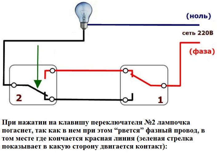
On the key of the pass-through switch there are two arrows (not large), directed up and down.
 This type is a pass-through single-key switch. There may be double arrows on the key.
 The connection diagram is not much more complicated than the connection diagram for a classic switch. The only difference is in the larger number of contacts: regular switch has two contacts, and the through one has three contacts. Two out of three contacts are considered common. In the lighting switching circuit, two or more similar switches are used.
 The differences are in the number of contacts
 The switch works as follows: when switching with a key, the input is connected to one of the outputs. In other words, the pass-through switch is designed for two operating states:
- The input is connected to output 1;
- The input is connected to output 2.
It has no intermediate positions, therefore, the circuit works as needed. Since the contacts are simply connected, in the opinion of many experts they should have been called “switches”. Therefore, a transition switch can be safely classified as such a device.
In order not to be mistaken about what kind of switch it is, you should familiarize yourself with the connection diagram, which is present on the switch body. Basically, the circuit is available on branded products, but you won’t see it on inexpensive, primitive models. As a rule, the circuit can be found on switches from Lezard, Legrand, Viko, etc. As for cheap Chinese switches, basically there is no such circuit, so you have to connect the ends with a device.

As mentioned above, in the absence of a diagram, it is better to call the contacts at different positions of the key. This is also necessary in order not to confuse the ends, since irresponsible manufacturers often confuse the terminals during the production process, which means that it will not work correctly.
To ring contacts, you must have either a digital or pointer device. The digital device should be switched to dialing mode. In this mode, short-circuited sections of electrical wiring or other radio components are determined. When the ends of the probes are closed, the device emits a sound signal, which is very convenient, since there is no need to look at the device display. If you have a pointer device, then when the ends of the probes are closed, the arrow deflects to the right all the way.
IN in this case It is important to find the common wire. For those who have the skills to work with the device, there will be no special problems, but for those who have picked up the device for the first time, the task may not be solvable, despite the fact that they only need to figure out three contacts. In this case, it is better to first watch the video, which clearly explains and, most importantly, shows how to do it.
Connection diagram for two pass-through switches
Such a scheme can provide significant assistance in organizing lighting on the stairs (in two-story house), in a long corridor or in a passage room. It can be quite convenient to organize lighting in the bedroom when one switch is installed at the entrance to the bedroom, and the other next to the bed. In this case, you won’t have to constantly get out of bed to turn off the main light.
 Electrical diagram connecting two pass-through switches
 The connection diagram is very simple and clear: a phase is supplied to the input of one of the switches, the input of the other switch is connected to one of the wires of the chandelier (lamp). The second end of the lamp is connected directly to the neutral wire. The N1 outputs of both switches are connected together, as are the N2 outputs.
The scheme operates quite simply. If you look at the diagram, in this position the light source is turned on. When you subsequently switch any of the switches, in any order, the lamp will turn off and on.
To make it more clear, you should carefully look at the figure.
 Wiring between two pass-through switches.
 If such switches are installed indoors, the wiring should be done as shown in the figure below. Modern requirements allow wiring at a distance of 15 cm from the ceiling. As a rule, wires are laid in special trays or boxes, and the ends of the wires are concentrated in installation (distribution) boxes. This approach has undeniable advantages. The main thing is that a damaged wire can always be replaced. The connection of wires in installation boxes is carried out using special clamps (contact blocks). At the same time, twists are also allowed, which are then necessarily soldered and reliably insulated.
The output of the second switch is connected to one of the conductors going to the lighting lamp. The white conductors are the wires connecting the outputs of both switches.
 Wiring in residential premises
 You can find out how the ends of the wires in the junction box are connected by watching the corresponding video.
Three-point lighting control option
If there is a need for remote control of the lamp from three places, then you will also have to purchase a cross switch. It switches not one, but two contacts at a time, so it has two inputs and two outputs.
How to connect all three switches can be seen in the figure. This is somewhat more complicated than the previous case, but you can understand the principle of operation.
 Electrical diagram for switching on a lamp from three places.
 To connect an electric light source, according to this diagram, you must perform the following operations:
- The neutral wire is connected to one of the lamp wires.
- The phase wire is connected to the input contact of one of the pass-through switches.
- The free wire of the lamp is connected to the input contact of the second switch (pass-through).
- The two output contacts of the pass-through switch are connected to the two input contacts of the crossover switch.
- Two output contacts of the second pass-through switch connect to the two output contacts of the cross switch.
The diagram is the same, but it is shown more clearly where exactly to connect the wires.
 Which terminals are the wires connected to?
 This is approximately how you should route the wires around the room.

Based on a circuit for three control points, you can assemble circuits for 4 or 5 points. In such cases, it is necessary to increase the number of crossover switches. They should always be installed between two pass-through switches.
 Scheme of organizing on/off lamp for 5 points.
 If you remove one of the cross switches from this circuit, you get a 4-point option, and if you add one cross switch to it, you get a 6-point option.
Two-key pass-through switch: connection diagram
In order to control the operation of two lamps from several points, there are two-key pass-through switches. They have six contacts. The main thing is to identify common contacts. They are determined according to the same principle as when searching for a common contact in single-key pass-through switches.
In a circuit that uses two two-key pass-through switches, significantly more wires are used.
The phase wire is supplied to the inputs of both switches, and the other inputs of the switches are connected to one of the ends of one and the other lamp. The free ends of the lamp are connected to the neutral conductor. The two outputs of one switch are connected to the two outputs of the second switch, and the other two outputs of that switch are connected to the other two outputs of the first switch.