Sometimes walls, even those made of brick or reinforced concrete slabs, fall into disrepair. And there can be many reasons for this: fire, time, the premises have not been inhabited for a long time, soil subsidence, design errors, the appearance of an unplanned load. The degree of damage to walls varies, and the progress of work required to reconstruct or strengthen them depends on it.
Gain Features
Before starting strengthening and repair work, it is necessary to establish the extent of the damage and, only then, begin work.
There are four levels of damage:
- weak (up to 15% of the wall surface is damaged);
- medium (up to 25% of the surface is damaged);
- strong (up to 50% of the surface is damaged);
- destroyed walls - more than 50% damage.
Advice. To determine the level of damage to the walls, or the speed of movement of cracks, you need to install beacons made of plaster (for internal walls) or cement (for external walls).
Cracks on external walls can change their width depending on the time of year: in winter they narrow, and in summer they widen.
Beacons are installed using the following technology: the surface of the wall where the beacons will be installed is cleaned and moistened. Strips of cement or gypsum are applied to it with a spatula (thickness 10*4*0.8 cm).
Advice. The thinner the beacon, the more accurately you can determine the speed of movement of the crack. It’s also better to install several beacons along the length of the crack.
After the beacons have dried, they are marked: a line is drawn along the beacon with a pencil, an observation notebook is kept, and the date of installation of the beacon is written down. To complete the picture, it is necessary to observe the lighthouse observers every day. With further growth of the crack, the beacon will be damaged (broken), and with further observation, you can find out the speed of its movement.
Strengthening with a strong foundation
The appearance of cracks did not occur due to design errors or improper foundation laying. There are several ways to eliminate them.
First way. The depth of the cracks is less than 5 mm. In this case, pour cement mortar or warm plaster with polystyrene. First, the crack is thoroughly cleaned and moistened, after which it is filled with fresh solution.
Second way. The depth of the cracks is more than 5 mm. For good result use metal staples.
Strengthening brick walls in this case it happens in the following order:
- the crack is cleaned and moistened;
- filled with a solution of cement and sand;
- along the crack at some distance from it, holes are drilled with a depth of 11 cm, a diameter of 2 cm, a step of 15-20 cm;
- the grooves serve as the basis of the brackets, the depth of which is 4 cm and the width is 3 cm (the grooves are attached with the mixture that was used to seal the crack);
- strengthen the staples.
Important. In order for the staples to serve for a long time, they must be processed and plastered. The same applies to gratings for strengthening walls.
Third way. For deep or through cracks, metal bridges are used (they are rigidly bolted on both sides of the crack), and then the damaged area is replaced.
Since metal conducts both current and cold well, it is necessary to insulate the walls along with restoration work.
Strengthening with cords
They are used if the verticality of the walls is disrupted with their subsequent collapse. For screeds, round reinforcement (25-30 mm in diameter) is used; they are screwed either to each other in the corners or to grooves that are installed at the joints of the walls (the second option is more reliable).
If the damage to the walls is more severe, then install clips from various materials:
- reinforced;
- reinforced concrete;
- compositional;
- steel.
This is what heavy weight looks like
The principle of strengthening walls is approximately the same: first, metal corners are installed and attached to the walls, then a mesh is made from various materials. The cells are attached to the wall with anchors (10-12 mm), or the connections are welded, or they are fastened to a metal mesh. After this, the mesh must be plastered with a cement mixture.
Reinforced concrete structures can also be reconstructed or strengthened. There are two types of such work: restoration of individual areas, or replacement of the protective layer (in whole or in part).
For partial restoration, use cement putty, having previously cleaned and moistened the surface. If it is necessary to carry out a major reconstruction or replacement of the protective layer, it is better to use gunite. If the structure is load-bearing, then the thickness of the protective layer is increased to 3 cm, and if it is not working, then to 2 cm.
Important. Before starting restoration work, it is necessary to clean the protruding fittings from rust.
Strengthening an opening in a wall - features of the process
Strengthening the opening
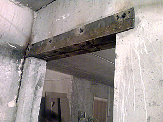
The walls are strengthened by dismantling part of the masonry and replacing it with a new one, or by inserting a steel plate or reinforced concrete slab gasket To carry out this work, support beams are installed strictly vertically in the opening.
Then they carefully dismantle part of the masonry, or insert a steel or reinforced concrete slab. Grooves are installed in the recess and grooves are attached to them, to which, in turn, a steel plate or reinforced concrete slab is attached. After its installation, it is covered with cement mortar. After the latter has completely dried, the supporting structure is disassembled.
The completion of the work is the complete restoration of the structures.
Repair work and strengthening of stone walls
Correct and effective method elimination of defects in stone walls can be selected only on the basis of a thorough analysis and elimination of the causes of their occurrence. The elimination of wall defects begins only after receiving the approved project. These works must be carried out in accordance with the work plan. The method of performing the work is chosen by the repair and construction organization.
The degree of damage to stone walls is assessed by their loss of bearing capacity and is divided into weak, medium and strong.
Light damage (up to 15%) are caused by defrosting, weathering and fire damage to the wall material to a depth of no more than 5 mm, as well as vertical and oblique cracks that cross no more than two rows of masonry.
Medium damage (up to 25%) caused by thawing and weathering of the masonry, peeling of the cladding to a depth of up to 25% of the thickness, fire damage to wall materials to a depth of up to 20 mm, vertical and oblique cracks crossing no more than four rows of masonry, tilting and bulging of walls within one floor by an amount not exceeding 1/5 of their thickness, forming vertical cracks at the intersection of longitudinal and transverse walls, local disturbances in the masonry under the supports of beams and lintels, displacement of floor slabs by no more than 20 mm.
Severe damage (up to 50%)- this is the result of the collapse of walls, defrosting and weathering of masonry to a depth of up to 40% of its thickness, fire damage to the wall material to a depth of 60 mm, vertical and oblique cracks (excluding temperature and sedimentation) to a height of no more than eight rows of masonry, tilting and bulging of walls within one floor by % of its height, displacement of walls and pillars along horizontal seams or oblique grooves, separation of transverse walls from longitudinal ones, damage to masonry under the supports of beams and lintels to a depth of more than 20 mm, displacement of floor slabs on supports by more than 40 mm.
Walls are considered destroyed, having lost more than 50% of their strength.
The need to eliminate the above damage serves as the basis for carrying out repair and restoration work.
Work on the repair and strengthening of stone walls includes: repairing building plinths, sealing cracks, repairing and strengthening lintels, strengthening individual piers and pillars, ensuring spatial rigidity of walls, relaying individual sections of walls, insulating walls, filling or constructing openings, reinforcing masonry walls by injection. .
In stone buildings, based on the size of the opening, there are narrow (1...5 mm), wide (5...40 mm) cracks that do not violate the integrity of the masonry, and cracks that have an opening value of more than 40 mm and violate the integrity of the masonry.
Narrow cracks are cleared (opened), washed with water and caulked with shotcrete.
Wide cracks, with an opening of 5...40 mm and not violating the integrity of the masonry, are sealed in the following order: the crack is cleared (opened) and washed with water, caulked with shotcrete.
Cracks that have an opening of more than 40 mm or that violate the integrity of the masonry are sealed in the following order: the crack is cleared (opened) and washed with water, caulked with shotcrete, then holes are drilled along the length of the crack, into which injectors are inserted, through which injector is pumped into the crack cavity under pressure special mixture.
Strengthening stone walls with clips.
First type clips (old technology) are arranged as follows (Fig. 1). The surface of the pillar or wall in the places where corner posts with a cross section of 120x120x10 mm and planks of 120x20 mm are installed is thoroughly cleaned of plaster and leveled in order to ensure their tight contact with the surface of the reinforced element. Rack corners are installed in the design position over a layer of cement-sand mortar with position fixation using wire twists or clamps. The joint operation of the holder and the reinforced element is ensured by creating prestressing strips welded to the corners. The simplest and reliable way creating prestress - thermal. It consists in the fact that the transverse strips are heated to a temperature of 150...200 ° C immediately before installation and, without allowing them to cool, are welded to the corners. The distance between the transverse strips should not exceed the thickness of the reinforced element.
Fig.1. Reinforcement of brick walls with steel frames at a ratio of width to thickness: a - 1.5; b - >1.5; 1 - opening; 2 - pier; 3 - corner L120x10; 4 - steel strip 120x20; 5 - coupling bolt
Second type clips are made from the same materials as the first type of clips, but the process of pre-heating the transverse bars, which is in modern construction conditions practically impossible. To create tension in the structure, special shotcrete is used, which tends to expand during crystallization. A combined method of installing clips, followed by shotcrete and injecting the mixture into the damaged masonry is often used to strengthen piers and pillars.
Reinforced mortar clips strengthen the walls by creating a volumetric stress state in them.
During the operation of buildings and structures, it becomes necessary to carry out repair work to ensure the stability and rigidity of walls. The main reasons for loss of stability of walls are significant deformations of the base or the possibility of their occurrence with increasing loads on the foundations, for example, when adding floors.
To increase the rigidity of the walls, steel ties are installed or reinforced concrete or steel belts are installed.
Installation steel strands(Fig.2) is the most effective method increasing the spatial rigidity of buildings with a degree of wall wear of no more than 60%. The ties are made of reinforcing steel class A-I diameter 30...38 mm. They are installed in grooves previously punched along the perimeter of the building at the level of the interfloor ceilings. At the corners of buildings, angle supports are installed, for example L 125x10. These supports protect the brickwork of the walls from local collapse and transmit compression forces over a large area. Tension of the strands is carried out using turnbuckles.

Fig.2. Reinforcement of walls with steel strands installed in the walls:
a - facade; b - plan; 1 - steel rod; 2 - turnbuckle; 3 - support angle
With another option for installing steel strands - across the building at the level of the floors of each floor or through the floor (Fig. 3). Steel bars are made of round, square or strip steel. When the length of the cord is more than 6000 mm, each strand can consist of two parts connected to each other using a lanyard. The end sections of the strands are passed through holes pre-drilled or punched in the outer walls. Then, alternately on both sides of the building, channel No. 16...20 is installed with a vertical shelf to the plane of the wall: outside or in a pre-punched groove. The ends of the strands, which have screw threads, are passed into the holes of the channels and two nuts are screwed on each side. The tension of the strands is carried out by screwing on the nuts, and if the length is long, then using lanyards. At a given design tension force, nuts and turnbuckles can be screwed using calibrated impact wrenches.

Fig.3. Reinforcement of walls with steel ties installed under the ceilings:
1 - wall; 2 - overlap; 3 - steel rod; 4 - distribution pad; 5 - lanyard (turnbuckle)
Reinforced concrete and reinforced brick belts (Fig. 4) are used mainly in the superstructure of buildings and structures. They serve to uniformly transfer loads to the underlying walls, absorb tensile forces arising from uneven settlement of the base, and ensure the overall rigidity of the building.

Fig. 10. Reinforcement of walls with stiffening belts:
a - reinforced concrete belt; b - reinforced seam; c - reinforced brick belt
The belts are placed at the level of interfloor ceilings in the form of continuous strips on all main walls, including transverse ones. The cross-section of the reinforcement is taken according to the design.
In case of external, not deep 10-40 mm destruction of the wall surface, application of shotcrete over a reinforcing mesh is used. The thickness of the layer of reinforced shotcrete is 30-60mm. Shotcrete, due to its low moisture permeability, reliably protects the wall from atmospheric influences.

If a crack in the wall of a building is slightly open, the most effective way to strengthen it is to install steel dowels. contraction brickwork occurs due to compression of the crack using a recessed steel key, which allows the crack to be evenly tightened on all sides, eliminating repeated destruction of the wall structures.

Figure 5 - Sealing a crack in a brick wall by installing dowels made of rolled metal; 1- reinforced wall; 2- a crack in the wall, up to 10 mm wide, injected with a mixture after installing the dowels; 3- fines in the wall; 4- key made of rolled metal (channel, angle); 3- cavities filled with shotcrete. The advantage of this method of strengthening is the possibility of its implementation without stopping production, with low costs of materials and without increasing the transverse dimensions of structures.
Repair and strengthening of reinforced concrete walls
When repairing the protective layer of concrete, the following types of work are provided:
Sealing of individual gouges and shells;
Replacement or restoration of the protective layer (partial or complete).
During a complete replacement, the thickness of the protective layer can be increased, but in all cases it must be at least 3 cm in clearance for working fittings and at least 2 cm for clamps and non-working fittings.
The protective layer of concrete is replaced in cases where its properties are reduced, the reinforcement is corroded, or the protective layer of concrete peels off. In these cases, the old protective layer must be completely removed, and the fittings must be cleaned of rust.
To repair minor damage to the protective layer, manual plastering techniques are used.
For a large volume of work, the most effective method of applying concrete is shotcrete, which achieves a very dense and durable protective layer.
Most often, brick walls require repair when cracks form in them.
The main reasons for the formation of cracks in the walls of a house:
- shrinkage of the building after construction for 1...1.5 years;
- deformation of foundations due to freezing and uneven thawing of groundwater;
- insufficient foundation depth;
- unequal bearing capacity of the soil within the house and, consequently, uneven settlement of its various parts;
- deformation of the beam floor;
- different loads on the soil of parts of the house, for example, an extension to the house without an expansion joint;
Causes of cracks in brick walls
Rice. 1. Insufficient foundation depth.
 Rice. 2. Subsidence of soil of unequal bearing capacity:
1 - soil of lower bearing capacity; 2 - soil with greater bearing capacity.
 Rice. 3. Formation of cracks in the walls due to deflection of the beam floor.
 Rice. 4. Formation of cracks in brick walls due to the lack of an expansion joint between the main building and the extension.
 Rice. 5. Formation of cracks in the walls due to the impact of increased loads on the floor structure. Cracks that are widened at the top are usually formed from the subsidence of the foundations on the side of the crack, while those that are widened at the bottom are usually formed from the subsidence of the middle part of the house.
 Rice. 6. Analysis of cracks in stone walls using paper tape fixations:
1, 2 - damage to the tape with large and small displacement, respectively; 3 - tapes without offset; 4 - crack.
A common cause of cracks is shrinkage of the house. To determine the causes and record the process of formation and enlargement of cracks, paper or plaster tapes are glued to them, indicating the date of attachment. If the tape does not break within a month or more, then the shrinkage has ended and the cracks can be repaired, but if it continues to tear, then we need to look for other reasons for the formation of cracks
Methods for repairing brick walls
 Rice. 7. Fastening designs when relaying large sections of the wall:
1 - bed; 2 - tightening; 3 - racks; 4 - lining under the racks (channel or wooden beam); 5 - metal beams;
A, B, C - zones of different loads during wall transformation.
Reinforcing the wall with metal plates
 Rice. 8. Gain brick wall metal pads when tearing off a corner.
 Rice. 9. Reinforcement of a brick wall with metal plates when tearing off a transverse wall.
 Rice. 10. Reinforcement of a brick wall with metal plates when the wall breaks.
If there is a small number of destructive cracks formed after the building shrinks, metal plates are installed on the outer and inner sides of the wall and secured with bolts.
Strengthening and replacing supports
 Rice. 11. Strengthening the support with brickwork:
1 - old support; 2 - new brickwork; 3 - fittings; 4 - strip steel; 5 - concrete; 6 - steel corners.
The damaged support is reinforced with brickwork, in every 4th bedding joint of which steel reinforcement with a diameter of 3...8 mm is laid.
The support can be strengthened with steel corners bound with strip steel, followed by lining with concrete.
In some cases, it is necessary to completely change the support. To do this, all structures that transfer loads to the support are strengthened with racks with braces, and then they are dismantled. The laying of the new support is carried out using cement mortar with reinforcement with a diameter of 3...8 mm placed in the bed joints in 3...5 rows.
 Rice. 12. Extension of load-bearing wall:
1 - using a multi-row horizontal fine; 2 - using small (one row) horizontal fines; 3 - using a vertical fine; 4 - extension of the wall without bandaging.
Extend load-bearing walls with and without bandaging. old load-bearing wall can be connected to the new one, if the new one is 1 floor high. To do this at the end old wall nests are cut down to a height of 3...5 rows of masonry, half a brick deep. The new wall is laid on cement mortar.
High walls are connected to old ones without dressing, laying out the seams with strips of roofing material to fit them more tightly to each other. You can also cut a vertical groove at the end of the old wall to ensure a tight fit between the old and new walls.
New slopes of window and door openings are connected by bandaging more carefully (after 1...3 bricks) due to the danger of separating the junction of the new and old walls.
Strengthening the walls
 Rice. 13. Strengthening the walls by increasing their cross-section:
1, 2 - new and old masonry, respectively.
 Rice. 14. Strengthening the walls with reinforced concrete corset:
1, 2 - piers reinforced with a reinforced concrete corset with an increase in the cross-section of the wall.
Strengthening the partitions between window and door openings is possible by increasing the cross-section of the partitions if the width of the opening is reduced. On one or both sides of the wall, new masonry is made using cement mortar, connecting it to the old dressing through 1...3 rows of bricks.
If it is impossible to reduce the width of the opening, then a reinforced concrete corset is installed. The surface of the corset entering the room is insulated with a layer of plaster.
When the partitions are completely rebuilt, the window openings are reinforced with posts with transverse ties.
The laying of new walls is carried out using cement mortar; if necessary, it is reinforced with a wire mesh.
Sealing cracks
 Rice. 15. Repairing cracks in a brick wall:
1 - new masonry; 2 - crack; 3-brick lintel.
Cracks can be repaired only after the walls have stopped deforming. Cracks up to 5 mm wide are filled with liquid cement mortar, after clearing them of dirt and rinsing them with water. For wider cracks, part of the masonry is dismantled and replaced with a new one, laying it out in the form of “ brick castle» from several rows of bricks on cement or mixed solution.
The outer disassembled sections of the wall are sealed with whole, well-burnt brick in a mixed mortar in a dressing with the old masonry.
After 1 m, sections of metal or reinforced concrete beams covering the cracks are embedded into the masonry.
Replacing weak areas of masonry
With a small number of cracks, weak areas are replaced with new masonry. The sections of the wall to be replaced are reinforced with metal bolts, supporting them with racks. The masonry is replaced one by one: first in the extreme areas, then in the middle and intermediate areas.
After the masonry is completed, the temporary fastenings are dismantled and the holes from the crossbars passing through the wall are sealed. The gap between the bottom of the metal beams and the new masonry is wedged with semi-dry cement mortar.

Rice. 16. Punching an opening in a load-bearing wall:
1 - stand; 2 - stand; 3 - jumper; 4 - opening in the wall; 5 - upper beam; 6 - wedges.
First, the floor is reinforced with beams, racks, supports and wedges.
The posts are nailed to the top beam with carpenter's staples. From the outside, the wall is reinforced with strips resting on stands secured with stakes driven into the ground.
Then a groove is cut out on one side and jumpers are inserted into it. The areas where the beams are supported are moistened with water, filled with cement mortar and sealed with brick or oak wedges. After the cement mortar has set, cut a groove for the remaining jumpers on the other side and install them in the same way.
After this, the masonry is finally disassembled according to the size of the opening.
REPAIR AND STRENGTHENING OF STONE WALLS
General information
Factors leading to the destruction of walls can be divided into two groups: force and influence-induced environment. Forces include: uneven settlements of the building, usually caused by a violation of the base under the foundation; increase in load due to the reconstruction or addition of buildings without proper consideration of the load-bearing capacity of the walls; violation of places of support; an increase in deflections of the lintels of window and door openings, etc. The influence of the environment is expressed in excessive moisture and subsequent freezing of walls, the aggressive effects of gases and dust particles contained in fumes from industrial enterprises and transport, weathering of wall materials and fire damage. The influence of biological factors leads to the destruction of walls made of organic building materials.
Extent of damage to stone walls are assessed by their loss of load-bearing capacity and are conventionally divided into weak, medium and strong.
Weak damage (up to 15%) is caused by defrosting, weathering and fire damage to the wall material to a depth of no more than 5 mm, vertical and oblique cracks crossing no more than two rows of masonry.
Moderate damage (up to 25%) is caused by defrosting and weathering of the masonry, peeling of the cladding to a depth of up to 25% of the thickness, fire damage to wall materials to a depth of 20 mm, vertical and oblique cracks crossing no more than four rows of masonry, tilting and bulging of walls within floors by an amount not exceeding 1/5 of their thickness, the formation of vertical cracks at the junction of longitudinal and transverse walls, local disturbances of the masonry under the supports of beams and lintels, displacement of floor slabs by no more than 20 mm.
Severe damage (up to 50%) is the result of wall collapse, defrosting and weathering of masonry to a depth of 40% of its thickness, fire damage to wall material to a depth of 60 mm, vertical and oblique cracks (excluding temperature and sedimentation) to a height of no more than eight rows of masonry, tilting and bulging of walls within a floor by 1/3 of their height, displacement of walls and pillars along horizontal seams or oblique cuts, separation of transverse walls from longitudinal ones, damage to masonry under the supports of beams and lintels to a depth of more than 20 mm, displacement of floor slabs on supports, amounting to more than 1/5 of the depth of their support.
Walls that have lost more than 50% of their strength are considered destroyed.
The need to eliminate the listed damage serves as the basis for repair work.
Work on repairing and strengthening walls includes: re-lining sections of walls; sealing cracks; strengthening masonry by injection; repair and strengthening of jumpers; strengthening of pillars and piers; ensuring spatial rigidity of buildings.
Restoration of walls and lintels
Relaying of individual sections of walls and replacement of fallen or weakened stones is carried out from top to bottom when dismantling old masonry and from bottom to top when making new masonry. At the same time, measures are taken to ensure the safety and stability of the position of the overlying sections of the wall and the structures resting on them.
The dismantling of the old and installation of new masonry begins after the installation of temporary fastenings, which are maintained for the entire period of work. To replace narrow partitions (up to 1 m), temporary fastenings are made from single posts resting on the bottom of the window or doorway and directly supporting the lintel elements, and for wide partitions (more than 1 m) - from paired posts installed on both sides of the opening. When installing temporary fastenings, ensure a tight fit of the top and bottom of the racks, as well as putting them into operation using wedges. In especially critical cases, the inclusion of temporary fastening posts in the work is controlled by measuring the deformation of the post during the process of knocking out wedges.
To unload the deformed area, unloading beams are used, which are driven into pre-punched grooves on both sides of the wall. First of all, the beam is placed on the weakest side of the wall. To do this, mark and punch a groove in the wall, the height of which should be 40...60 mm greater than the height of the unloading beam. Next, prepare areas for supporting the beam on masonry with a depth of at least 250 mm and install the beam. The gap between the upper surface of the beam and the masonry is caulked with rigid cement mortar. On the other side of the wall, these operations are performed 2... 3 days after installation and sealing of the first beam.
Simultaneous re-laying of walls in several tiers vertically and access of people to the underlying premises is prohibited.
The sizes of the stones used for repairs must correspond to the sizes of the stones of the masonry being repaired. They must be close in their physical and mechanical properties. For the construction of new walls, materials (brick, concrete stones, etc.) of increased strength, not lower than grade 100, are used.
The composition and brand of the solution must meet the requirements of the project. The solution is used before setting begins. If it has separated during transportation, it must be thoroughly mixed before use. Depending on the purpose, the solution must have mobility, determined by a standard cone: for walls and pillars made of brick - 80...130; hollow brick walls -70...80; wedge lintels -50...60 mm.
Horizontal joints between rows of brickwork and vertical joints between bricks in lintels, piers and pillars are filled with mortar. When laying hollow bricks, the depth of the joints not filled with mortar on the front side should not exceed 15 mm for walls and 10 mm (only vertical joints) for pillars. The seams at the junction of the old and new masonry are carefully filled with mortar and caulked. The top of the new masonry is not brought up to the old one by 30...40 mm; this gap is caulked with a rigid cement mortar of a grade not lower than 100. In some cases, to ensure an increased density of the junction of the new masonry with the old one, it is allowed to drive flat steel wedges into the unhardened mortar.
Sealing cracks widths up to 40 mm are made with cement mortar. Before filling with mortar, the crack is thoroughly cleaned of dust and dirt, and the brick walls are generously moistened with water. After the brick absorbs water, the surface of the crack is treated with cement laitance, then sealed with a plastic cement mortar of 1:3 composition prepared with Portland cement. The quality of work will improve if the solution is injected into cracks under pressure up to 0.145 MPa. Moreover, depending on the pressure, the water-cement ratio of the solution can range from 0.7 to 0.3. The location of the holes for supplying the solution depends on the nature and location of the cracks. On vertical and inclined cracks, holes are placed every 0.8...1.5 m, on horizontal cracks - every 0.2...0.3 m.
When repairing cracks with a width of more than 40 mm, replace the masonry along the cracks for the entire thickness of the wall and for a width of 380...510 mm, strictly observing the bandaging of the seams.
Masonry in places of cracks is dismantled without preliminary: fastening individual sections or the entire wall in cases where the height of the crack does not exceed 0.5 of the floor height, if horizontal loads or loads are not transmitted to the wall; applied with significant eccentricities, as well as if the cracks are located at a distance of at least 3 m from each other. In all other cases, repair of cracks begins only after ensuring the stability of the walls for the entire period of work. Metal anchors, connections and other elements are preserved during disassembly without compromising their integrity.
To strengthen through cracks and cracks in the form of gaps at the junctions of walls, metal plates made of strip steel are used. Overlays, as a rule, are installed on both sides of the wall and tightened together with bolts. In places where the walls meet, the linings, extended along the length with bolts, are passed through perpendicularly located walls and anchored.
Enhancement by injection consists of feeding cement or polymer-cement mortar under pressure into the damaged masonry, which, penetrating into the cracks and crevices, after hardening ensures the necessary solidity of the masonry.
When preparing solutions for injection, use Portland cement grade no lower than 400 (grinding fineness - no less than 2400 cm/g, normal density of cement paste - 22... 25%) and Portland slag cement grade 400, which has a low viscosity in liquefied solutions, as well as sand - fine with a fineness modulus of 1.0... 1.5 and finely ground, the grinding fineness of which approaches the grinding fineness of cement. Sodium nitrite (5% of the cement mass), PVA polyvinyl acetate emulsion (polymer cement ratio - 0.05), naphthalene-formaldehyde (melamine-formaldehyde) additive (10% of the cement mass) are used as plasticizing additives.
To carry out the work, cement (sandless), cement-sand, cement-polymer and polymer solutions are used, which must have insignificant water separation, a given viscosity, the required strength, low shrinkage and sufficient frost resistance.
for masonry with cracks opening up to 1.5 mm - polymer solutions based on epoxy resin (for 100 kg of epoxy resin ED-20 (ED-16) take 30 kg of MGF-9 modifier, 15 kg of PEPA hardener and 50 kg of finely ground sand); cement-sand mortars with the addition of finely ground sand of composition 1: 0.1: 0.25 (cement: naphthalene-formaldehyde: sand) at W/C = 0.6;
for masonry with crack openings of 1.5 mm or more - cement-polymer mortars of composition 1: 0.15: 0.3 (cement: PVA polymer: sand) at W/C = 0.6; cement-sand mortars (sand fineness modulus - 1) composition 1: 0.05: 0.3 (cement: sodium nitrite: sand) at W/C = 0.6; cement (sandless) solutions of composition 1: 0.1 (cement: naphthalene formaldehyde) at W/C = 0.5.
The composition of injection solutions is prescribed in accordance with the requirements of the project and adjusted taking into account local conditions and the materials used.
The solution is prepared in the following sequence: Portland cement and finely ground sand, dosed by mass, are mixed dry and poured into a mortar mixer, where a plasticizer dissolved with part of the water included in the solution is added, then the rest of the water is added. The prepared mixture is stirred for 10 minutes, after which it is filtered through a vibration filter. Before injection, the prepared solution is stored with continuous stirring.
The solution is pumped into the masonry under pressure up to 0.6 MPa. The filling density of the masonry during the injection process of the solution is controlled by the radius of its distribution (flow out of the nozzles, wetting of the plaster).
When repairing stone or brick lintels above the openings cracks are sealed (if they are slightly open), partial or complete relaying is performed, reinforced with rolled steel profiles, and if the lintels fail, they are completely replaced.
Small cracks in the lintels, carefully caulk the outer surface, moisten it with water and, after absorbing the water, fill it with liquid cement mortar. After the solution has set, the tow is removed from the cracks. On unplastered facades, the remaining recesses are filled with plastic cement mortar and the seams are opened; on plastered facades, the recesses are filled during the process of restoring the plaster layer.
For partial or complete relaying of jumpers they install window or door openings and unload the lintel by placing temporary fastenings under it. Particular attention is paid to the installation of temporary fastenings when located directly above the lintel of floor beams, the position of which is fixed with special fastenings. After strengthening the wall, the lintel is replaced with a new one. Laying is done according to traditional scheme- from the heel to the castle. The brand of mortar and brick is adopted according to the project. The bottom row of ridge and reinforced stone lintels is laid out with butts. Wedge and arched lintels made of ordinary brick can be laid on the wedge without processing it due to the installation of vertical joints of variable thickness. The minimum thickness of such a seam is 5, at the top - 25 mm.
Strengthening lintels with rolled steel profiles(Fig. 1) are produced using a technology similar to that described above. If, when strengthening with angles, it is necessary to cover a significant span or strengthen a lintel damaged in the middle of the span, the working span of the angle is reduced by installing strip steel ties. The rods are usually installed on both sides and connected to each other with bolts. When strengthening lintels in external walls, measures are taken to preserve their heat-shielding properties, since cold bridges are formed in places where metal passes through. Steel profiles, used to strengthen the jumpers, are inserted into the wall at least 250 mm on each side and installed on a pre-prepared bed.

Fig.1 Strengthening jumpers:
A - overlaying corners and bringing in beams;
b- reduction of the span of cords;
1 - corner;
2 - concreted channel;
3 - bolt;
4 - strip steel tie rod
Replacing a faulty jumper on a steel or prefabricated reinforced concrete frame is carried out after it has been completely unloaded and the floor structures resting on this lintel have been secured. Work begins from the weakest side of the wall, where, according to preliminary markings, a horizontal groove is punched, the height of which is 40...60 mm greater than the height of the installed lintel. The furrows are cleared of crushed stone, dirt and dust, then thoroughly washed with water. Metal beams made of channels and I-beams are pre-filled with bricks, which are fastened with wire, wound around the beam. The new lintel is installed in the design position on a bed of rigid cement mortar and fixed in this position with wedges. If the lintel is not installed to the full thickness of the wall, the resulting space between the inner surface of the lintel and the wall is filled with plastic mortar. External cracks are caulked with hard cement mortar. Work on the opposite side of the wall begins no earlier than 5...6 days after installing the lintel in the first furrow. Jumpers that do not fill the entire thickness of the wall are bolted together.
Strengthening pillars and piers,
ensuring spatial rigidity of buildings
Reinforcement of pillars and walls with clips- a very effective way to increase the load-bearing capacity of repaired structures.
According to the nature of their work, clips can be divided into three types:
1) restraining transverse deformations; the load-bearing capacity increases as a result of the creation of a volumetric stress state in the reinforced element;
2) perceiving part of the normal forces transmitted to the reinforced element; the desired effect is achieved by increasing the cross-sectional area or introducing into the existing dimensions a material with increased physical and mechanical properties;
3) combined, simultaneously performing the functions of clips of the first and second types.
Depending on the type of material used, the cages are steel, reinforced concrete and reinforced mortar.
Steel clips are the easiest to manufacture; consist of vertically installed corner posts and strips of strip or round steel connecting them (Fig. 2, A).

Fig.2 Clip arrangement:
a, b - steel types 1 and 2, respectively;
V- reinforced concrete;
1 - stand corners;
2 - connecting strips;
3 - pinch bolt;
4 - fittings (not shown on the façade)
The main disadvantage of steel frames is the risk of cold bridges appearing when installing them on external walls. To avoid this, additional thermal insulation measures are taken.
Type 1 clips are arranged as follows. The surface of the pillar or wall where the corner posts are installed is thoroughly cleaned of plaster and leveled to ensure a tight fit of the corners to the surface of the reinforced element. The corners are installed in the design position on a thin layer of cement-sand mortar and fixed with wire twists or clamps. The joint work of the frame and the wall or pillar is ensured by the pre-stressing of the strips welded to the corners. The simplest and most reliable way to create prestress is thermal. To do this, the transverse strips are heated to a temperature of 150...200 °C immediately before installation, then, without allowing them to cool, they are welded to the corners. The distance between the cross bars should not be less than the thickness of the reinforced element
Type 2 clips are also made from corner posts and transverse bars, the pitch of which should not exceed 40 radii of inertia of the corner smallest profile in the clip. The most critical stage in installing clips of this type is putting them into operation. Since the cage is designed to absorb and transmit vertical loads, it is necessary to ensure sufficient support area for the corner at the top and bottom. To do this, a bed of hard cement mortar of grade no lower than 100 is arranged in the place where the clips are supported. To include the clip in the work, steel wedges are driven under the supports. In the most critical cases, the forces created in the vertical elements are controlled by the deformations of the corners. After achieving the specified deformations, the cage is maintained until the appearance of crushing deformations at the supports and the appearance of plastic deformations, then the wedges are finally tapped and their position is fixed.
The second way to include type 2 clips in the work is to prepare the pillar angles longer than the distance between the upper and lower supports, and install them in place, slightly bending along the length (Fig. 2, b). The tension is created as a result of the alignment of the corners with coupling bolts located along the height of the cage. Having installed in the design position, the corners are connected to each other by transverse strips. The length of the corner posts is determined immediately before installing them in place, based on the actual dimensions between the supporting platforms, the specified level of prestress and the physical and mechanical properties of the material.
Clips of the 3rd type (combined) are installed in the design position in compliance with the rules for installing clips of the 1st and 2nd types.
The greatest effect of strengthening piers, pillars and damaged sections of walls can be achieved by simultaneously installing clips and injecting cement mortar into the damaged masonry.
After installation, the steel cages are protected from corrosion by a layer of cement mortar 25...30 mm thick over a metal mesh.
Reinforced concrete cage(Fig. 2, V) It is a thin slab covering the perimeter of the reinforced element. The thickness of the clip is determined by calculation (40mm). The formwork configuration takes into account the possibility of restoring quarters of the openings. If you need to save without changing cross section a wall whose masonry is in satisfactory condition, before installing the frame, it is cut off at the ends to the thickness of the frame. In this case, the pier is unloaded by installing temporary supports. To maintain or slightly change the dimensions of the opening, it is allowed to reduce the thickness of the frame to 30...40 mm.
Concrete for the cages must be of grade no lower than 150; it is prepared on crushed stone with a maximum fraction of 10mm. It is advisable to make reinforcement from factory-made meshes and frames. The distance between the clamps should not exceed 150 mm. When the aspect ratio of the reinforced wall or column is more than 1:2.5, the reinforcing mesh located on the larger side is connected to each other.
Concrete is placed into the formwork in layers, carefully compacting each layer by vibration. High quality work is achieved by constructing frames made of shotcrete, each subsequent layer of which no more than 10 mm thick is applied after the previous one has set. The number of layers applied is determined by the designed thickness of the casing.
Before concreting, the reinforced structure is thoroughly cleaned of buildup, plaster layer, dirt and debris to ensure adhesion of the concrete frame to the structure material. It is recommended to moisten brick walls and pillars with water before starting concreting.
In reinforced concrete cages of the 1st type, compression of a pillar or wall occurs due to a decrease in the dimensions of the cage as a result of shrinkage of freshly laid concrete. Type 2 clips are put into operation by carefully caulking the gaps between the top of the clip and the bottom of the existing structure with hard cement mortar. If necessary, steel wedges are driven into the gaps after the concrete has reached 70% of its design strength. Type 3 clips are made in compliance with all the above requirements.
Reinforced mortar clips performed similarly to reinforced concrete, only instead of concrete, the reinforcement is covered with a layer of grade 75 cement mortar
When installing such clips, quarters in window openings do not need to be removed. It is enough to drill holes and pass through them the clamps located at the ends of the wall. The meshes installed in the design position are connected to each other by welding and wedged to ensure the specified thickness of the protective layer. Plastering is done in layers by hand or by shotcrete. The thickness of the plaster layer on the reinforcement must be at least 20 mm. As with the installation of reinforced concrete cages, to maintain dimensions window openings it is allowed to reduce the thickness of the holder on the end surfaces of the walls.
As a rule, reinforced mortar clips strengthen the walls due to the volumetric stress state created in them. The use of such clips to absorb normal forces is impractical due to the insignificant thickness of the cement mortar layer.
Work to ensure the stability and rigidity of building walls begin after stabilization and elimination of the causes of the deformations that caused the violations. In some cases, when building superstructures, the walls are reinforced to prevent undesirable phenomena when the load on the foundations increases.
To restore the performance qualities of the walls, pre-stressed steel strands are installed, and reinforced concrete or reinforced brick belts are installed.
Installation of prestressed steel ties(Fig. 3) is one of the effective methods of increasing the spatial rigidity of buildings. Ties made of round reinforcing steel with a diameter of 28...38 mm are installed in grooves punched along the perimeter of the building at the level of the interfloor ceilings. The supports of the ties at the corners of buildings are corners that protect the masonry walls from local collapse and transmit compression forces to a large area. Tension is performed using turnbuckles; it can be effectively combined with thermal tension.

Fig.3 Installation of steel ties:
A - building's facade;
b- plan;
1 - steel ties;
2 - turnbuckles
The results of the introduction of prestressed steel strands indicate the cost-effectiveness of this method, achieved as a result of replacing expensive and labor-intensive work on strengthening foundations and foundations with relatively easy-to-perform work, as well as its reliability. The use of steel ties is advisable for capital buildings, the wear of the walls does not exceed 60%.
Reinforced concrete and reinforced brick belts(Fig. 4) are used, as a rule, when adding buildings or increasing operational loads, which can cause uneven settlement of buildings. Such belts serve to uniformly transfer the load to the underlying walls of the building, absorb tensile forces arising from uneven settlement, and maintain the overall rigidity of the building while increasing the strength of the walls.

Fig.4 Wall reinforcement:
A - reinforced concrete belt;
b- reinforced seam;
1 - corner;
2 - reinforced brick belt
The belts are placed at the level of interfloor ceilings in the form of continuous strips lying on all main walls, including transverse ones. The belts must have a reliable connection with the walls. The cross-section of the reinforcement in them is taken according to the design; it should be within 6...10 cm depending on the section of the belt.
Reinforced concrete belts are not placed across the entire thickness of the external walls in order to preserve them thermal properties. On interior walls belts can be throughout the entire thickness of the walls. When the belts intersect with channels located in the walls, holes are made in the belts for the passage of communications.
In case of minor deformations of the walls, reinforced seams or reinforced brick belts are used. Reinforced seams are made with a thickness of 50...60 mm around the perimeter of all main walls. The amount of reinforcement is the same as for the installation of reinforced concrete belts. The effectiveness of a reinforced seam is greatly enhanced by the transition to a reinforced brick belt, which consists of two reinforced seams located above each other through 4...6 rows of brickwork and interconnected by vertical rods.
Quality control and acceptance of completed work
Quality of wall repair work achieved with careful adherence to production technology, application quality materials and organization of operational control (Tables 1, 2).
The materials used for repairs should be similar in their characteristics to the materials of the wall being repaired. To a depth of 1/3 of the thickness or more, the wall is dismantled after unloading it and ensuring the strength and stability of the repaired area. The system for bandaging seams on the sections of the wall being re-laid must correspond to the existing one.
Map of operational quality control of wall repair work
|
Works subject to control |
Methods and means of control |
Control time |
|
|
Preparatory work |
Unloading of structures, compliance with the design, thoroughness and reliability of fastenings |
Visually |
Before work starts |
|
Compliance with the quality and type of materials (brick, mortar) | |||
|
Removing window and door frames from plastered slopes |
Visually | ||
|
Pre-laying work |
Width of masonry disassembly when repairing through cracks |
Folding meter |
Before laying begins |
|
Installation of fines, driving in metal pins to ensure connection between old and new masonry |
Visually; folding meter | ||
|
Cleaning the surface from dust and dirt |
Visually | ||
|
Brickwork |
Wetting the surface with water |
Visually |
In the process of laying |
|
Thickness and thoroughness of filling seams |
Visually | ||
|
Compliance with the suture dressing system |
Visually | ||
|
Compliance with geometric dimensions, verticality and horizontality |
Folding meter, plumb line |
Prohibited:
when repairing walls, use hardened and dehydrated solutions; moisten silicate, slag, ash and ash bricks; moisten clay bricks and ceramic stones when laying on lime and lime-clay mortars prepared with air-lime;
when reinforcing pillars and piers with clips, use a pneumatic tool to dismantle the masonry; install transverse steel strips without prestressing.
Permissible deviations, mm (Fig. 5):
|
1 - cut marks | |
|
2 - width of openings | |
|
3 - vertical surface (unevenness when applying a 2-meter strip): | |
|
plastered wall | |
|
unplastered wall | |
|
4 - surfaces of corners from the vertical: | |
|
the entire height of the wall | |
|
5 - masonry thickness | |
|
6 - width of the walls | |
|
7 - rows of masonry from the horizontal at a length of 10 m | |
|
8 - pitch of transverse bars | |
|
9 - surfaces and corners from the vertical to the entire height of the wall | |
|
10 - marks of the bottom of the opening |

Fig.5 Schemes for determining permissible deviations:
A - when repairing walls;
b- when installing clips;
Map of operational quality control of work on the installation of clips
|
Works subject to control |
Controlled parameters, processes and operations |
Methods and means of control |
Control time |
|
Preparatory work |
Reliability and compliance with the design of unloading structures |
Visually |
Before work starts |
|
Cleaning the smooth surface from dust and dirt |
Visually | ||
|
Wetting masonry with water |
Visually | ||
|
Type and quality of materials (brick, mortar) |
Visually; laboratory tests | ||
|
Installation of steel cages |
Workpiece dimensions |
Folding meter |
In progress |
|
The tightness of the corners to the surface |
Visually | ||
|
Heating temperature of cross bars |
Visually | ||
|
Quality of welded joints |
Visually | ||
|
Installation of reinforced concrete frames |
Availability of tags and certificates on fittings |
Visually | |
|
Correspondence of the location of the reinforcement to the project |
Folding meter | ||
|
Dimensions and reliability of formwork | |||
|
Laying and compacting concrete |
Visually | ||
|
Caring for freshly laid concrete |
Visually |
During the acceptance process take into account permissible deviations, basic prohibitions and a list of operations documented in acts for hidden work.
Acts for hidden work are drawn up:
when repairing walls - the condition of the structures being preserved; anchoring and protection of steel elements from corrosion; depth of completeness of filling with masonry mortar during injection;
when reinforcing pillars and piers with clips - work related to welding of transverse strips; protection steel structures from corrosion; compliance of the installed fittings with the design; compaction of concrete.
Electronic document text
prepared by Kodeks JSC and verified based on materials
provided by Ph.D. (VITU)
Tkachev Sergey
The inspection of stone and reinforced masonry structures is carried out taking into account the requirements of SNiP 11-22-81 “Stone and reinforced masonry structures”, as well as “Recommendations for strengthening masonry structures of buildings and structures”.
Before the examination stone structures it is necessary to identify their structure by highlighting the load-bearing elements. It is especially important to take into account the actual dimensions of load-bearing elements, the design diagram, evaluate the magnitude of deformations and destruction, identify the conditions for supporting beams, slabs and other bendable elements on the masonry structure, the condition of the reinforcement (in reinforced masonry structures) and embedded parts. The size and nature of defects and the presence of typical damage (chips and cracks) directly depend on the above conditions.
For strength determination In masonry, mechanical tools and devices are used, as well as ultrasonic devices. Using hammers and chisels through a series of blows, you can approximately assess the qualitative condition of the stone and concrete structures. More accurate data is obtained using special hammers, i.e. mechanical devices based on the assessment of traces or results of impacts on the surface of the structure being tested. The simplest, although less accurate, tool of this type is the Fizdel hammer. A ball of a certain size is pressed into the striking end of the hammer. By means of an elbow strike, creating approximately the same force different people, a trace-hole remains on the surface under study. According to the size of its diameter c. Using a calibration table, the strength of the material is assessed .
More precision instrument is the Kashkarov hammer, when using which the force of the ball hitting the material under study is taken into account by the size of the mark on a special rod located behind the ball.
But the most modern and accurate instruments of mechanical action are spring ones: a device from the Academy of Communal Services of the RSFSR, the Central Research Institute building structures. The operating principle of these devices is based on taking into account a certain impact force caused by the release of a charged spring. A device of this type is a housing in which a spiral spring is placed, connected to a hammer rod. After pressing the trigger, the spring is released and the firing pin strikes. In the TsNIISK device, the impact force can be set to 12.5 or 50 kg/cm 2 for stone materials of varying strength.
To determine the bends and deformations of vertical surfaces, their shape and the nature of deviations from verticality and plane, use a level with a special attachment that allows sighting, starting from 0.5 m instead of the minimum 3.5 m when there is no nozzle.
The relief of vertical surfaces is revealed by the method of sighting the instrument from one of its positions on the rail, applied horizontally to pre-designated points of the surface being examined. The results of measuring deformations of horizontal or vertical surfaces are plotted on diagrams on which, for clarity, lines of equal deviations from the horizontal or vertical are revealed, like horizontals planes. The cross-section is given equal to 2-5 mm depending on the degree of deviation or violation of the position or local defects of the element being examined and its overall dimensions.
However, first of all, it is necessary to find out the nature of the negative changes in the masonry and determine whether the process of crack formation has stabilized, or whether their number and opening width are increasing over time. For this purpose, they are installed in the masonry itself beacons. The beacon is a strip of plaster, glass or metal that covers both sides of the crack. Lighthouses made of plaster and glass will burst if the deformation that caused the cracks continues.
| Instruments for diagnosing the strength of a material: a - Fizdel hammer; b something Kashkarova; c - TsNIISK pistol: 1 - calibrated ball; 2 - angular scale; 3 -
calibration table; 4-replaceable rod for fixing the impact mark |
|
 |
Measuring vertical surface deformations using a level with an optical attachment: a-plan; b- wall surface; c - section; 1 - level; 2 - rail; 3 - places where the slats are applied; 4 - lines of equal deviations from the plane |
 |
Beacons for monitoring the condition of cracks: /-crack; 2-plaster and alabaster mortar; 3- wall material; 4- plaster beacon; 5 - glass lighthouse; 6 - metal plate; 7 - marks every 2-3 mm; 8 - nail |
By measuring the magnitude of the divergence of the halves of the beacon, the nature of the change in the crack or its stabilization is determined. A metal beacon is attached to one side of the crack, and it can move along its other edge, along its other side, where the initial and subsequent positions of the end of the beacon are recorded. The simplest beacon is paper beacon, which is a strip of paper glued to a crack; with further expansion of the crack, the paper beacon breaks.
Cracks in load-bearing masonry structures correspond to the stages of crack formation (or stages of masonry operation under compression). With efforts in masonry F
, not exceeding the effort Fcrc
, in which cracks appear in the masonry, the structure has a load-bearing capacity sufficient to withstand the existing load, cracks do not form. Under loads F  Fcrc
the process of crack formation begins. Since masonry does not resist tension well, there are cracks on stretched surfaces (areas)
Fcrc
the process of crack formation begins. Since masonry does not resist tension well, there are cracks on stretched surfaces (areas)
appear much earlier than the possible destruction of the structure.
The main reasons for the formation of cracks are:
1) poor quality of masonry (poor mortar joints, non-compliance with dressings, backfilling in violation of technology, etc.);
2) insufficient strength of the brick and mortar (cracks and curvilinearity of the brick, non-compliance with the drying technology during its manufacture; high mobility of the mortar, etc.);
3) the combined use in masonry of stone materials of different strength and deformability (for example, clay bricks together with silicate bricks or cinder blocks);
4) use of stone materials for purposes other than their intended purpose (for example, sand-lime brick in conditions of high humidity);
5) low quality of work performed in winter time(use of bricks that have not been cleared of ice; use of frozen mortar, absence of anti-frost additives in the solution);
6) failure to make temperature-shrinkable seams or an unacceptably large distance between them;
7) aggressive environmental influences (acid, alkaline salt exposure; alternating freezing and thawing, moistening and drying);
8) uneven settlement of the foundation in the building.
It is no coincidence that the foundation settlements are indicated last condition for the occurrence of cracks in masonry. It should be borne in mind that during the period of mass construction in masonry, mortars without antifreeze additives were used, thin, non-plastic, i.e. very cheap. All this contributed to abundant education shrinkage
cracks that must be separated from the clean surface during examination sedimentary
cracks that have a specific, easily identifiable character.
Let's consider the process of crack formation in masonry during compression
First stage- the appearance of the first hair cracks in individual stones. An effort Fcrc
at which cracks appear at this stage depends mainly on the type of mortar used in the masonry:
- in masonry with cement mortar F crc = (0.8 - 0.6) F u ; ;
- in masonry with complex mortar F crc = (0.7 - 0.5) F u ;
- in masonry with lime mortar F crc = (0.6 - 0.4) F u ,
Where F u—
destructive force.
Second stage— germination and unification of individual cracks. This stage begins and proceeds more intensely along the southern facade of the building, which experiences the greatest temperature fluctuations in the atmospheric environment. In addition, the growth of cracks is observed when external drains are improperly organized or their system is disrupted in places where the masonry periodically gets wet.
Third stage– further formation of large surfaces of destruction and exhaustion of the strength of the masonry.
 |
 |
|
The photograph shows a structure with an attic resting on an internal transverse wall. On the free part of the roof, a slope was created for an organized external drainage system, but the corner of the building was significantly wetted. The arrow points to a developing crack that appeared after one year of operation of the reconstructed structure. |
Defects in brickwork and their causes: a-wear from 20 to 40%; b-wear 41-60%; c- overloaded walls with wear up to 40%; d - the same, with greater wear; d - exposure of brickwork due to wear of plaster |
When analyzing the pattern of cracks, it should be remembered that the appearance of individual cracks in the dressing stones indicates overstress in the masonry. Crack development in the second stage indicates significant overstressing of the masonry and the need to unload or strengthen it.
When large destruction surfaces form, it is advisable to replace the masonry with a new one or strengthen it with a structure that can fully withstand the operational load.
During the operation of the structure, cracks may open due to an unreasonably long length of the temperature block or due to the absence of a temperature-shrinkage seam at all. During the period of reconstruction with the construction of bay windows, hanging elevators, installing additional and attic floors Cracks may appear in the masonry due to the insufficient area of support of the lintels on the wall and the low strength of the masonry, from overloading the pier and the low strength of the masonry. There are other possible causes of cracking. For example, chaotically located cracks often occur in structures that are in close proximity to the place where piles are driven, or in old buildings, the wear of the brickwork reaches 40% or more.
Strength bricks and stones must be determined in accordance with the requirements of GOST 8462-85, solution— GOST 5802-86 or SN 290-74. The density and moisture content of masonry is determined in accordance with GOST 6427-75, 12730.2-78 by establishing the difference in the weight of the samples before and after drying. The frost resistance of stone materials and mortars, as well as their water absorption, is established according to GOST 7025-78.
Samples for testing are selected from lightly loaded structural elements, provided that the materials used in these areas are identical. Samples of bricks or stones must be intact without cracks. Irregularly shaped stones are cut into cubes with edge sizes ranging from 40 to 200 mm or drill out the cylinders (cores) diameter from 40 to 150 mm. To test solutions, cubes are made with an edge from 20 to 40 mm, composed of two mortar plates glued together with gypsum mortar. Samples are tested for compression using standard laboratory equipment. Areas of brick (stone) from which samples were taken for testing must be completely restored to ensure the original structure.
Technology for restoring and strengthening brickwork
As noted above, the brick buildings of mass-produced residential buildings had high reliability and a significant margin of safety. But long service life, violations technical specifications contents could cause significant damage to load-bearing brick walls. Depending on the visible damage and condition of the structures, the loads acting on them, and other factors that impede normal operation, during reconstruction measures are taken to restoration load-bearing capacity of brickwork. In addition, when increasing the number of floors of a structure or otherwise increasing the construction volume of a structure, the need arises for strengthening brick structures.
Recoverybearing capacity of masonry comes down to sealing and localizing cracks. Naturally, this problem must be solved after identifying and eliminating reasons that caused cracking:
1) eliminate or stabilize uneven foundation settlements by strengthening foundations or foundations;
2) change the conditions for transferring the load to the cracked pier in order to redistribute the load over a larger area;
3) redistribute the loads to other (or even additional) structures in case of insufficient strength of the masonry itself.
It should be noted that sealing cracks should also accompany measures to strengthening brick structures, which are necessary when loads increase and it is impossible to redistribute them to other elements of the structure.
Technologically, sealing cracks in brick walls can be done using one of the following methods or a combination of them.
Injection of cracks - injection of solutions of liquid cement or polymer-cement mortar, bitumen, resin into cracks in damaged masonry. This method of restoring the load-bearing capacity of masonry is used depending on the type of structure, the nature of its further use, the available injection capabilities, and most importantly, if the crack is local and has a small opening. It can be done using various materials. Depending on their type, they distinguish silicatization, bitumenization, smolization And cementation. Injection allows not only to monolith the masonry, but also to restore and, in some cases, increase its load-bearing capacity, which occurs without increasing the transverse dimensions of the structure.
The most widely used are cement and polymer-cement mortars. To ensure injection efficiency, use Portland cement grade of at least 400 with a grinding fineness of at least 2400 cm 2 /g, with a cement paste density of 22 - 25%, as well as Portland slag cement grade 400 with low viscosity in liquefied solutions. Sand for the solution is used fine with a fineness modulus of 1.0 - 1.5 or finely ground with a grinding fineness of 2000-2200 cm 2 /g. To increase the plasticity of the composition, plasticizing additives in the form of sodium nitrite (5% by weight of cement), polyvinyl acetate PVA emulsion with a polymer cement ratio P/C = 0.6 or naphthalene-formaldehyde additive in the amount of 0.1% by weight of cement are added to the solution. .
Quite stringent requirements are imposed on injection solutions: low water separation, required viscosity, required compressive and adhesive strength, low shrinkage, high frost resistance.
At small cracks in a clutch (up to 1, 5 mm) use polymer solutions based on epoxy resin (epoxy ED-20
(or ED-16) - 100 wt.h.; modifier MGF-9 — 30 wt.h.; hardener PEPA – 15 parts by weight; finely ground sand - 50 wt.h), as well as cement-sand mortars with the addition of finely ground sand (cement - 1 parts by weight; superplasticizer naphthalene-formaldehyde – 0.1 parts by weight; sand - 0.25 parts by weight; water-cement ratio – 0.6).
At more significant opening of cracks use cement-polymer solutions of composition 1:0.15:0.3 (cement; PVA polymer; sand) or 1:0.05:0.3 (cement: plasticizer sodium nitrite: sand), W/C = 0.6 , sand fineness modulus M k =1. The solution is injected under pressure up to 0.6 MPa. The density of crack filling is determined 28 days after injection.
The solution is injected through injectors with a diameter of 20-25 mm. They are installed in special drilled holes after 0.8-1.5 meters along the length of the crack. The diameter of the holes should ensure installation of the injector tube on the cement mortar. Hole depth – no more 100 mm, the injector tube is fixed in the hole with caulked tow.
 Injecting cracks up to 10 mm wide with cement-sand mortar:
1- masonry; 2- crack; 3- holes for injectors every 800-1500 mm; 4- steel injector tube; 5- tow, caulked with glue; 6- solution supply
Installation of reinforcing steel brackets
used in methods for restoring the bearing capacity of masonry when cracks open more 10 mm. To do this, a recess is made in the masonry using a milling cutter to the size of the bracket. The bracket is secured with bolts along the edges, the crack itself is usually injected with cement-sand mortar and caulked with a rigid mortar.
Installation of brackets made of reinforcing steel: 1-reinforced wall; 2-crack in the wall, injected with cement-sand mortar after installing brackets; 3-brackets made of reinforcing steel; 4-groove in the masonry, selected with a milling cutter; 5-recesses at the ends of the groove, made with a drill; 6-filling grooves and recesses with cement-sand mortar
At significant damage masonry a network of cracks staples perform double-sided, in this case the masonry experiences double-sided compression. Development of numerous end-to-end cracks can be stopped by using a staple instead strip steel plates , which are installed in increments of 1.5-2 wall thicknesses.
|
|
|
|
|
|
|
|
|
Double-sided brackets made of reinforcing steel with bolts: 1- masonry; 2- through crack; 3- linings made of strip steel; 4- coupling bolts; 5 holes in the wall |
||


The damage can be so significant that in some cases partial dismantling and re-building of the destroyed brickwork is required. Typically this is done with the device inserts of brick locks equipped with an anchor .
 |
Wide, more 10 mm, crack ( 1 ) intercepted by a one- or two-sided overlay ( 2) , no longer made of strip steel, but of rolled metal, which is attached to the wall with anchor bolts. In this case, the overlay is called anchor. Along the entire length of the development of the crack, the damaged brick is removed to a thickness of two bricks and replaced with reinforced masonry on cement-sand mortar, called brick castle (3-4
).
|
 |
Partial or complete filling of openings with masonry: 1- reinforced partition; 2- window openings; 3- reinforced brickwork of grade M75-100 on mortar M50-75; 4- seam, wedged with a metal plate and caulked with cement-sand mortar |
 |
Scheme for unloading brick walls: 1 - jumpers, 2 - boards 50-60 mm; 3- racks with a diameter of more than 20 cm; 4 - wooden wedges; 5- temporary fastening of racks |
Increased load-bearing capacity and stability of the walls can be ensured increasing cross-sectional area
, device of various clips
or metal frame.
Increasing cross-sectional area The wall is reached by increasing its width. In this case, new sections of masonry are laid out on both sides of the wall, which is securely tied to the old one, and, if necessary, reinforced. Damaged load-bearing walls are unloaded, the cross-sectional area of the walls increases, and the area of window openings decreases accordingly, therefore window units subject to replacement.
When leaning on a reinforced wall truss structure or the wall deviates from the vertical by more than 1/3 of the thickness of the brick, the wall is first unloaded by placing temporary wooden or metal pillars on gypsum mortars.
Main ways reinforcement of brickwork,
are well-tested methods of device clips, build-ups
or shirts,
divided into reinforced concrete
And mortar
. When amplified reinforced concrete frames, jackets And build-ups class B10 concrete and class A1 reinforcement are used, the transverse reinforcement spacing is taken to be no more than 15 cm. The thickness of the holder is determined by calculation and varies from 4
before 12 cm.
Mortar clips, shirts And building up, also called plastering, differ from reinforced concrete because they use grade 75-100 cement mortar, which protects the reinforcement reinforcement.
Construction of a reinforced concrete frame effective in case of surface destruction of the material of piers and pillars to a small depth or when deep cracks occur, when widening of the piers is possible. In the first case, the destroyed sections of the pier are cleared to a depth of at least the thickness of the reinforced concrete casing, and the section of the pier does not change as a result of its construction. In the second case, the cross-section of the pier is increased due to the installation of a reinforced concrete cage.
The technological process of installing a reinforced concrete frame of piers consists of removing window fillings, clearing damaged areas or cutting down the pier to the required depth, removing window quarters, installing reinforcement, installing formwork, concreting, maintaining concrete, removing formwork and dismantling scaffolding. The working reinforcement of a reinforced concrete cage can be pre-stressed by heating up to 100-150° C (for example, heating by electric current).
 |
Construction of reinforced concrete frames: a-without increasing the cross-section of the pier; b-with magnification sections pier |
 |
|
 |
Construction of a pre-stressed plaster frame: 1-reinforced wall; 2-metal plates with holes for cords; 3-strand-connections; 4 holes in the wall for cords; 5-reinforcing bars welded to the plates and tightened in pairs; 6- plaster made of cement-sand mortar; 7-reinforcement mesh tied to bars |
Instead of reinforcing cages when reinforcing, it is possible to use wire mesh with a diameter of 4-6 mm with cell 150x150 mm. In both cases of reinforcement, both meshes and frames are attached to the reinforced surface with pins (anchors).
For large areas, additional tie clamps are installed in steps of no more than 1m at medium length75 cm.
The formwork of the reinforced concrete frame is built up from the bottom up during the concreting process. To construct reinforced concrete frames, the shotcrete method is used, in which formwork is not required. In this case, it is applied under pressure to the reinforced surface of the wall. concrete mixture using a cement gun. The advantage of this method of constructing a reinforced concrete frame is the mechanization of the concreting process. The reinforced concrete cage increases the load-bearing capacity of the element enclosed in it by 2 times
 |
|
|
Reinforced concrete frame clamps: 1- reinforced wall surface; 2- fittings with a diameter of 10 mm; 3- tie clamps with a diameter of 10 mm; 4 - holes in the masonry; 5 - concrete frame; 6- reinforcement cages |
|
 |
 |
| Construction of a plaster or reinforced concrete jacket: 1-reinforced wall; 2-armholes; 3-plaster jacket 30-40 mm or reinforced concrete jacket 60-100 mm thick; 4-reinforcement with a diameter of 10 mm; 5-reinforcement with a diameter of 12 mm; 6-metal pins | Construction of a reinforced concrete core: 1-reinforced wall; 2-openings; 3-post (core) made of reinforced concrete;
4-niche cut into the pier; 5-reinforcement frame; 6-concrete |
Mortar shirts and extensions
differ from clips only in one design feature - they are made one-sided. The shirt can be made not over the entire width of the wall - in the form core.
Sometimes steel clips for reinforcing brickwork on constantly used buildings are left without protective coating mortar or concrete, arranging metal carcass
gain.
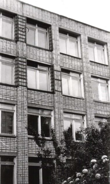 |
 |
| Reinforcement of piers with a metal frame: a- narrow pier; b- wide pier; 1-brick element; 2-steel corners; 3-bar; 4-cross link |
|
 |
Construction of overhead belts from corners: 1-reinforced partition; 2-corners of overhead belts; 3-cross bars; 4-pin bolts; 5-plaster with cement-sand mortar on a metal mesh |
The construction of a metal frame of piers is less labor-intensive and material-intensive than the construction of a reinforced concrete frame, and is widely used.
Preparation for the installation of metal frames of piers consists of unloading the piers, removing the filling of window openings and cutting down the quarters. With this method, corner steel racks are installed at the corners of the piers to their full height and tightly adjusted to the piers, which are connected after 30-50 cm in height with strip steel, butt-welded to the corner flanges. Then the wall is covered with wire metal mesh and plastered.
The metal frame can be placed on the wall or embedded flush into it. In the second case, before installing the frame, the corners of the walls are cut off and horizontal grooves are punched in the places where the metal connecting strips are installed.
After installing the frame, the gaps between metal elements and the wall is carefully caulked with mortar. If the lintels resting on the pier are also destroyed, it becomes more effective to strengthen the pier by adding racks from the corners. In this case, the racks are made slightly longer than the distance between the lintel and the floor. At the top they are attached to the exposed reinforcement of the jumpers, and at the bottom to an overhead belt made of channel, mounted on the body of the object being reconstructed. The racks are straightened in pairs with clamps, thus creating pre-stress. Straightening, breaks, cuts in the flanges of the corners are welded.
Gain corners buildings are also advisable to produce using channel overlays length 1.5-3 m. Overlays can be placed on both the outer and inner surfaces of the wall. They are connected to the brickwork using tie bolts installed in pre-drilled holes. The coupling bolts are located along the height of the reinforced part of the masonry through 0.8-1.5 m.
|
|
Connecting the racks from the corners: 1-reinforced partition; 2-openings; 3-racks of unequal corners, curved to the side; 4-break lines; 5-fold part; 6-exposed reinforcement; 7-welding; 8-solution |
|
|
|


If local deformations occur and to prevent further crack opening, it is carried out by strengthening interface zones longitudinal and transverse walls of the building unloading beams . Unloading beams are installed in previously punched grooves on one or both sides of the wall at the level of the top of the foundation or lintels of the first floor.
Double-sided beams through 2-2.5 m connected by bolts with diameter l6-20 mm, passed through previously drilled holes in the beams and wall. One-sided beams are installed on anchor bolts, the smooth ends of which are secured in the wall by installing them with cement mortar into previously drilled sockets. Beam connections with bolts are secured with nuts. Step anchor bolts 2-2.5 m.
The gaps between the flanges of the beams and the brickwork are carefully caulked with cement mortar of a composition of 1:3. For the manufacture of unloading beams, a channel or I-beam No. 20-27 is used. In places where walls break, cracks are installed on each floor using clamps made from rolled metal scraps no less than 2 m. Before installing the bracket-screed, a groove is cut into the wall so that the screed is installed flush with the surface of the brick wall. Holes for bolts are drilled in the wall and in the screed according to the markings. 20- 22 mm, with the help of which the bracket-screed is attached to the wall. The distance from the crack to the bolt installation site must be at least 70 cm. Before installation, the tie-brace is wrapped with wire mesh or wire. 1-2 mm. After installing the structure, the crack and the fine are carefully sealed with a brand solution M100.
 |
 |
|
Installation of metal plates (frame) when reinforcing a building: 1-deformed building; 2-cracks in the walls of the building; 3-linings made of channels or metal plates; 5-pin bolts; 6-fine for installing plates, sealed with mortar; 7-holes in the walls for bolts, after installing the bolts they are caulked with mortar |
Typically, development cracks related to uneven settlement of foundations, requires additional measures not only to increase the load-bearing capacity of the masonry, but the rigidity of the entire structure as a whole. Gross violation of masonry technology, unacceptable operating conditions of the structure, as in the case of uneven settlement of foundations, cause not only the development of cracks at window and door openings, but also violations of the verticality of enclosing structures.
In places tearing off external walls from internal ones to restore the rigidity of the building, connections are made from metal frames or reinforced concrete dowels. In this case they say that the building reinforced.
However, most often, after eliminating the causes of uneven settlement of the foundation, the building needs tightening the body generally. Perhaps the only way to do this is to creation of tension belts .
 |
 |
 |
 |
Construction of external stress zones: 1-deformed building; 2-steel rods; 3-roll profile from angle No. 150; 4 turnbuckles; 5-weld seam; 6- cracks in the walls of the building; 7-hole in the wall filled with cement-sand mortar
It should be emphasized here that the most common mistake in strengthening the body brick buildings with a hard design diagram is the creation vertical stiffening discs(laying in or reducing the area of window openings, installing vertical metal frames, etc.), while the most important thing here is horizontal stiffening disc. The tension belt, also called "bandage", is made from reinforcing bars with a diameter 20-40 mm connected by turnbuckles.
In rare cases, rolled steel is used instead of reinforcement. The result is a reinforcing element that absorbs both tensile and compressive forces, called spacer connection. Spacer ties are installed at the roof level and at the level of interfloor ceilings; they can be located both on the outside and on the inside of the structure.
 |
 |
 |
|
| Construction of internal stress zones: 1-deformation building; 2-steel rods with nuts; 3-metal plates; 4 turnbuckles; 5-holes in the walls, which are sealed with mortar after packing the strands; 6-cracks in the walls of the building | |
Strengthening interfloor ceilings residential buildings of series 1-447 is determined by the presence of short cracks and fragmentation of brick stone in the places where the floor slabs support. The main cause of destruction is usually an insufficient support area for the floor slab or the absence of a distribution pad.
The most effective amplification technique is installation technology steel rods And spacer ties under the floor slab, since, as already noted, the creation of a horizontal rigidity disk in buildings of this type is of paramount importance. However, this is a very expensive and time-consuming method; it is only possible with complete reconstruction with resettlement of residents. Therefore, they try to fulfill local strengthening damaged structures.
Local reinforcement, depending on the type of floor slabs, during partial or phased reconstruction is carried out by:
—increasing the support area of the beam using metal or reinforced concrete racks, the force from which is transmitted outside the destruction zone;
-increasing the support area of the slab by means of a belt fixed in the zone of destruction of the masonry;
- devices under the end of the floor slabs of reinforced concrete pads.
Calculation of brick elements reinforced with reinforcement and clips
Longitudinal reinforcement , designed to absorb tensile forces in eccentrically compressed elements (at large eccentricities), in bending and tensile elements, in reinforcing brickwork during reconstruction, is quite rare, so it is not considered in this section. However, with the growth seismic danger of some areas of central Russia due to underground workings and other anthropogenic factors, as well as when laying railways and highways near residential areas, longitudinal reinforcement is used when lining thin (up to 51 cm) brick walls of reconstructed buildings.
Mesh reinforcement masonry sections significantly increases the load-bearing capacity of reinforced elements of stone structures (pillars, piers and individual sections of walls). The effectiveness of mesh reinforcement during reinforcement is determined by the fact that reinforcing meshes laid in the horizontal seams of masonry sections prevent its transverse expansion during longitudinal deformations caused by acting loads, and thereby increase the load-bearing capacity of the masonry body as a whole.
Mesh reinforcement is used to strengthen masonry made of bricks of all types, as well as ceramic stones with slot-like vertical voids with a row height of no more than 150 mm. Reinforcement of concrete and masonry with mesh reinforcement natural stones with a row height of more than 150 mm little effective.
For masonry with mesh reinforcement, mortars of grade 50 and higher are used. Mesh reinforcement is used only for flexibility or, as well as for eccentricities located within the core of the section (for rectangular sections e 0<0,33 y). При больших значениях гибкостей и эксцентрицитетов сетчатое армирование не повышает прочности кладки.
For example, it is required to determine the cross-section of longitudinal reinforcement for a brick pillar 51 x 64 cm, height 4.5 m. The pillar is made of ordinary clay bricks of plastic pressing brand 100
on brand solution 50
. In the middle section of the column, the reduced calculated longitudinal force acts N p=25 t, applied with eccentricity e o =
25 cm towards the side of the section having size 64 cm.
We reinforce the column with longitudinal reinforcement located in the tension zone outside the masonry. We reinforce the compressed zone of the cross section of the column structurally, since when the reinforcement is located externally, frequent installation of clamps will be required to prevent buckling of the compressed reinforcement, which will require additional waste of steel. The installation of structural reinforcement in the compressed area is mandatory, as it is necessary for attaching the clamps.
Cross-sectional area of the pillar F=51 x 64 = 3260 cm 2. R=l5 kgf/cm 2(at F > 0.3 m 2). Design resistance of longitudinal reinforcement made of steel class A-1R a =l900 kgf/cm 2.
We take stretched reinforcement from four rods with a diameter of 10 mm F a =3.14 cm 2.
Determine the height of the compressed section zone X at h 0 =65 cm, e=58 mass media b=51 cm:
1.25-15-51 x (58-65+)-1900 -3.14-58 = 0,
and from the resulting quadratic equation we determine x= 35 cm<
0.55h o =36 cm.
Since the condition is satisfied, the load-bearing capacity of the section is determined by at =1000:
pr = = =7
hence = 0.94.
Section bearing capacity
0.94(1.25 x 15 x 51 x 35-1900 x 3.14) =25.6 t >N p =25 t.
Thus, with the adopted reinforcement cross-section, the bearing capacity of the column is sufficient.
Complex structures are made of masonry reinforced with reinforced concrete working together with the masonry. It is recommended to place reinforced concrete with outside masonry , which allows you to check the quality of the laid concrete, the grade of which should be taken to be 100-150.
Complex structures are used in the same cases as masonry with longitudinal reinforcement. In addition, it is advisable to use them, just like mesh reinforcement, to strengthen heavily loaded elements under axial or eccentric compression with small eccentricities. The use of complex structures in this case makes it possible to sharply reduce the cross-sectional dimensions of walls and pillars.
Elements reinforced with clips are used to strengthen pillars and piers having a square or rectangular cross-section with an aspect ratio of no more than 2.5. The need for such reinforcement arises, for example, when adding existing buildings. Sometimes it is necessary to strengthen masonry that has cracks or other defects (insufficient strength of the materials used, poor quality of masonry, physical wear, etc.)
Clips, as well as mesh reinforcement, reduce transverse deformations of masonry and thereby increase its load-bearing capacity. In addition, the clip itself also absorbs part of the load.
In the previous sections, three types of clips were considered: steel, reinforced concrete and reinforced plaster .
Calculation of elements made of brickwork, reinforced with clips, under central and eccentric compression at small eccentricities (not beyond the core of the section) is carried out according to the formulas:
with steel frame
N n [(m to R + ) F+R a F a ];
with reinforced concrete frame
N n [(m to R + ) F+m b R pr F b +R a F a ];
with reinforced plaster casing
N (m R + ) F.
The values of the coefficients are accepted:
at central compression=1 and =1;
with eccentric compression (by analogy with eccentrically compressed elements with mesh reinforcement)
1 — , where
N p - reduced longitudinal force; F- masonry cross-sectional area;
F a- cross-sectional area of the longitudinal corners of the steel cage installed on the mortar, or the longitudinal reinforcement of the reinforced concrete cage;
f b - cross-sectional area of the concrete cage enclosed between the clamps and the masonry (excluding the protective layer);
R a - design resistance of the transverse or longitudinal reinforcement of the cage;
- buckling coefficient, when determining the value A accepted as for unreinforced masonry;
t to - masonry operating conditions coefficient; for masonry without damage t to=1; for masonry with cracks t to =0,7;
t b - concrete operating conditions coefficient; when transferring the load to the holder from both sides (bottom and top) t b
=1; when transferring the load to the holder from one side (bottom or top) t b=0.7; without direct load transfer to the holder t b =0,35.
- percentage of reinforcement determined by the formula
x 100,
Where f x- cross-section of the clamp or crossbar;
h And b- dimensions of the sides of the reinforced element;
s- distance between the axes of the transverse bars with steel cages ( hs b, but no more than 50 cm.) or between clamps for reinforced concrete and reinforced plaster clamps (s15 cm).
For example, in the middle section of the pier measuring 51x90 cm, located on the ground floor of the building, after completion of the construction of the superstructure, the calculated longitudinal force will apply N n =60 t applied with eccentricity e O = 5 cm, directed towards the inner edge of the wall. The partition is made of sand-lime brick grade 125 with mortar grade 25. The height of the wall (from the floor level to the bottom of the precast reinforced concrete floor) is 5 m. It is necessary to check the load-bearing capacity of the wall.
Pier section F= 51 x 90 = 4590 cm 2 > 0.3 m 2.
Design resistance of masonry R = l4 kgf/cm 2. Distance from the center of gravity of the section to its edge in the direction of eccentricity
y = = 25.5 cm; = =0.2<0,33,
the eccentricity is within the core of the section. We design the wall for eccentric compression with low eccentricity. The elastic characteristics of sand-lime brick masonry on mortar grade 25 is = 750.
Reduced flexibility of the wall np == 11.3.
Buckling coefficient = 0.85.
Coefficient taking into account the influence of eccentricity = 0.83.
Let us determine the load-bearing capacity of the pier:
0.85 x 14 x 4590 x 0.83 = 45,200kgf
Since the load-bearing capacity of the wall turned out to be insufficient, we reinforce it with a frame made of steel isosceles angles measuring 60x60 mm, d=6 mm. The corners are installed on the mortar in the corners of the wall and connected to each other by strips of strip steel with a section of 5x35 mm, welded to the corners at a distance s=50 cm along the height of the wall.
Next, we determine the load-bearing capacity enhanced pier. Coefficient of masonry operating conditions t k =1. Design resistance of steel strips R a =1500 kgf/cm 2. Sectional area of the plank f x= 0.5x3.5= 1.75 cm 2. Design resistance of the corners of the cage (the load is not transferred to the corners) R a =430 kgf/cm 2. Sectional area of corners F a=6.91x4=27.6 cm 2. Next, we determine the coefficients and , =0,83, =1-=0,61 and the corresponding percentage of reinforcement: =x100=0.21%
Hence the load-bearing capacity of the reinforced wall will be:
0.83.0.85[(14 +0.61хх)4590+430 x27.6]=63800kgf > N p =60000 kgf
The load-bearing capacity of the reinforced wall is sufficient. 