Heating a house, garage, office, or retail space is an issue that needs to be addressed immediately after the premises are built. And it doesn’t matter what time of year it is outside. Winter will come anyway. So you need to make sure that it’s warm inside in advance. For those who buy an apartment in multi-storey building, there is nothing to worry about - the builders have already done everything. But those who are building their own house, equipping a garage or a separate small building will have to choose which heating system to install. And one of the solutions will be a vortex heat generator.
Air separation, in other words, its division into cold and hot fractions in a vortex jet - a phenomenon that formed the basis of a vortex heat generator was discovered about a hundred years ago. And as often happens, for about 50 years no one could figure out how to use it. The so-called vortex tube was modernized with the most different ways and tried to integrate it into almost all types of human activity. However, everywhere it was inferior both in price and efficiency to existing devices. Until the Russian scientist Merkulov came up with the idea of running water inside, he established that the temperature at the outlet increased several times and called this process cavitation. The price of the device has not decreased much, but the coefficient useful action became almost one hundred percent.
Operating principle

So what is this mysterious and accessible cavitation? But everything is quite simple. While passing through the vortex, many bubbles are formed in the water, which in turn burst, releasing a certain amount of energy. This energy heats the water. The number of bubbles cannot be counted, but the vortex cavitation heat generator can increase the water temperature up to 200 degrees. It would be stupid not to take advantage of this.
Two main types
Despite the fact that every now and then there are reports that someone somewhere has made a unique vortex heat generator with their own hands of such power that it is possible to heat an entire city, in most cases these are ordinary newspaper canards that have no basis in fact. Someday, perhaps, this will happen, but for now the principle of operation of this device can only be used in two ways.
Rotary heat generator. The centrifugal pump housing in this case will act as a stator. Depending on the power, holes of a certain diameter are drilled across the entire surface of the rotor. It is due to them that those same bubbles appear, the destruction of which heats the water. This type of heat generator has only one advantage. It's much more productive. But there are significantly more shortcomings.
- This installation is very noisy.
- Increased wear of parts.
- Requires frequent replacement of seals and seals.
- Too expensive to service.
Static heat generator. Unlike the previous version, nothing rotates here, and the cavitation process occurs naturally. Only the pump works. And the list of advantages and disadvantages takes a sharply opposite direction.
- The device can operate at low pressure.
- The temperature difference between the cold and hot ends is quite large.
- Absolutely safe, no matter where it is used.
- Fast heating.
- Efficiency 90% and above.
- Can be used for both heating and cooling.
The only disadvantage of a static WTG can be considered the high cost of the equipment and the associated rather long payback period.
How to assemble a heat generator

With all these scientific terms, which can scare a person unfamiliar with physics, it is quite possible to make a VTG at home. Of course, you will have to tinker, but if everything is done correctly and efficiently, you can enjoy the warmth at any time.
And you have to start, as in any other business, by preparing materials and tools. You will need:
- Welding machine.
- Sander.
- Electric drill.
- Set of wrenches.
- Set of drills.
- Metal corner.
- Bolts and nuts.
- Thick metal pipe.
- Two threaded pipes.
- Connecting couplings.
- Electric motor.
- Centrifugal pump.
- Jet.
Now you can start working directly.
Installing the engine
An electric motor, selected in accordance with the available voltage, is installed on a frame, welded or assembled with bolts, from a corner. The overall size of the frame is calculated in such a way that it can accommodate not only the engine, but also the pump. It is better to paint the frame to avoid rust. Mark the holes, drill and install the electric motor.
Connecting the pump
The pump should be selected according to two criteria. Firstly, it must be centrifugal. Secondly, the engine power must be enough to spin it up. After the pump is installed on the frame, the action algorithm is as follows:
- In a thick pipe with a diameter of 100 mm and a length of 600 mm, an external groove of 25 mm and half the thickness must be made on both sides. Cut the thread.
- On two pieces of the same pipe, each 50 mm long, cut the internal thread to half the length.
- On the side opposite to the thread, weld metal caps of sufficient thickness.
- Make holes in the center of the lids. One is the size of the nozzle, the second is the size of the pipe. It is necessary to chamfer the inside of the hole for the nozzle using a large-diameter drill so that it looks like a nozzle.
- The nozzle pipe is connected to the pump. To the hole from which water is supplied under pressure.
- The heating system input is connected to the second pipe.
- The outlet from the heating system is connected to the pump input.
The cycle is complete. Water will be supplied under pressure to the nozzle and, due to the vortex formed there and the resulting cavitation effect, will begin to heat up. The temperature can be adjusted by installing a ball valve behind the pipe through which water flows back into the heating system.
By closing it slightly, you can increase the temperature and vice versa, by opening it, you can lower it.
Let's improve the heat generator
This may sound strange, but this one is quite complex design can be improved, further increasing its performance, which will be a definite plus for heating a private home large area. This improvement is based on the fact that the pump itself tends to lose heat. This means that you need to make it spend as little as possible.
This can be achieved in two ways. Insulate the pump using any suitable materials for this purpose. thermal insulation materials. Or surround it with a water jacket. The first option is clear and accessible without any explanation. But we should dwell on the second one in more detail.
To build a water jacket for the pump, you will have to place it in a specially designed hermetically sealed container that can withstand the pressure of the entire system. Water will be supplied exactly to this container, and the pump will take it from there. The external water will also heat up, which will allow the pump to work much more efficiently.
Vortex absorber
But it turns out that’s not all. Having thoroughly studied and understood the operating principle of a vortex heat generator, you can equip it with a vortex damper. A stream of water supplied under high pressure hits the opposite wall and swirls. But there can be several of these vortices. One has only to install a structure inside the device that resembles the shank of an aircraft bomb. This is done as follows:
- From a pipe of slightly smaller diameter than the generator itself, you need to cut two rings 4-6 cm wide.
- Weld six metal plates inside the rings, selected in such a way that the entire structure is as long as a quarter of the length of the body of the generator itself.
- When assembling the device, secure this structure inside opposite the nozzle.
There is and cannot be a limit to perfection, and the vortex heat generator is still being improved in our time. Not everyone can do this. But it is quite possible to assemble the device according to the diagram given above.
Due to high prices for industrial heating equipment, many craftsmen are planning to make an economical vortex heat generator with their own hands.
Such a heat generator is just a slightly modified centrifugal pump. However, in order to assemble such a device yourself, even if you have all the diagrams and drawings, you need to have at least minimal knowledge in this area.
Principle of operation
The coolant (most often water is used) enters the cavitator, where an installed electric motor spins it and dissects it with a screw, resulting in the formation of bubbles with vapor (the same happens when a submarine and a ship are sailing, leaving behind a specific trace).
Moving along the heat generator, they collapse, due to which thermal energy is released. This process is called cavitation.
Based on the words of Potapov, the creator of the cavitation heat generator, the operating principle of this type of device is based on renewable energy. Due to the absence of additional radiation, according to the theory, the efficiency of such a unit can be about 100%, since almost all the energy used is spent on heating water (coolant).
Creating a wireframe and selecting elements
 To make a homemade vortex heat generator, to connect it to the heating system, you will need an engine.
And the greater its power, the more it will be able to heat the coolant (that is, it will produce more heat faster and more). However, here it is necessary to focus on the operating and maximum voltage in the network that will be supplied to it after installation.
When choosing a water pump, you need to consider only those options that the engine can spin. At the same time, it must be of a centrifugal type, otherwise there are no restrictions on its choice.
You also need to prepare a frame for the engine. Most often it is a regular iron frame into which iron corners are attached. The dimensions of such a frame will depend, first of all, on the dimensions of the engine itself.
 After selecting it, it is necessary to cut the corners of the appropriate length and weld the structure itself, which should allow placing all the elements of the future heat generator.
Next, to mount the electric motor, you need to cut out another corner and weld it to the frame, but this time across. The final touch in preparing the frame is painting, after which you can already attach the power plant and pump.
Heat generator housing design
 Such a device (a hydrodynamic version is being considered) has a body in the form of a cylinder.
It is connected to the heating system through through holes located on its sides.
But the main element of this device is the nozzle located inside this cylinder, directly next to the inlet.
Note: it is important that the size of the nozzle inlet is 1/8 of the diameter of the cylinder itself. If its size is less than this value, then water will physically not be able to pass through it in the required quantity. In this case, the pump will become very hot due to high blood pressure, which will also have a negative impact on the walls of the parts.
How to make
 For creating homemade generator heat you will need a grinder, an electric drill, and a welding machine.
The process will proceed as follows:
- First you need to cut a piece of a fairly thick pipe, with a total diameter of 10 cm and a length of no more than 65 cm. After this, you need to make an external groove of 2 cm on it and cut a thread.
- Now, from exactly the same pipe, you need to make several rings, 5 cm long, after which an internal thread is cut, but only on one side (that is, a half ring) on each.
- Next you need to take a sheet of metal with a thickness similar to the thickness of the pipe. Make lids out of it. They need to be welded to the rings on the side where they do not have threads.
- Now you need to make central holes in them. In the first, it should correspond to the diameter of the nozzle, and in the second, to the diameter of the pipe. At the same time, on the inside of the cover that will be used with the jet, you need to make a chamfer using a drill. Eventually the injector should come out.
- Now we connect a heat generator to this entire system. The pump hole, from where water is supplied under pressure, must be connected to the pipe located near the nozzle. Connect the second pipe to the entrance to the heating system itself. But connect the output from the latter to the input of the pump.
Thus, under the pressure created by the pump, the coolant in the form of water will begin to flow through the nozzle. Due to the constant movement of the coolant inside this chamber, it will heat up. After this, it goes directly into the heating system. And in order to be able to regulate the resulting temperature, you need to install a ball valve behind the pipe.
A change in temperature will occur when its position changes if it allows less water to pass through (it will be in a half-closed position). The water will stay and move inside the housing longer, causing its temperature to increase. This is exactly how a similar water heater works.
Watch the video where they are given practical advice for making a vortex heat generator with your own hands:
Have you noticed that the price of heating and hot water supply has increased and you don’t know what to do about it? The solution to the problem of expensive energy resources is a vortex heat generator. I will talk about how a vortex heat generator works and what is the principle of its operation. You will also find out whether it is possible to assemble such a device with your own hands and how to do it in a home workshop.
A little history
The vortex thermal generator is considered a promising and innovative development. Meanwhile, the technology is not new, since almost 100 years ago scientists were thinking about how to apply the phenomenon of cavitation.

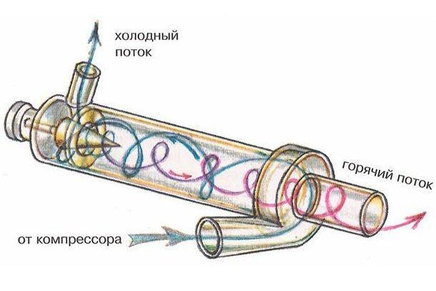
The first operational pilot plant, the so-called “vortex tube”, was manufactured and patented by the French engineer Joseph Rank in 1934.
Rank was the first to notice that the temperature of the air at the inlet to the cyclone (air purifier) differs from the temperature of the same air stream at the outlet. However, on initial stages bench tests, the vortex tube was tested not for heating efficiency, but, on the contrary, for the cooling efficiency of the air stream.

The technology received new development in the 60s of the twentieth century, when Soviet scientists figured out how to improve the Ranque tube by running liquid into it instead of an air jet.
Due to the higher density of the liquid medium, compared to air, the temperature of the liquid, when passing through the vortex tube, changed more intensively. As a result, it was experimentally established that the liquid medium, passing through the improved Ranque tube, heated up abnormally quickly with an energy conversion coefficient of 100%!
Unfortunately, there was no need for cheap sources of thermal energy at that time, and the technology did not find practical application. The first operating cavitation installations designed to heat a liquid medium appeared only in the mid-90s of the twentieth century.

A series of energy crises and, as a consequence, increasing interest in alternative sources energy served as the reason for resuming work on effective converters of the energy of movement of a water jet into heat. As a result, today you can buy a unit required power and use it in most heating systems.
Operating principle


Cavitation makes it possible not to give heat to water, but to extract heat from moving water, while heating it to significant temperatures.

The design of operating samples of vortex heat generators is externally simple. We can see a massive motor, to which is connected a cylindrical snail device.
"Snail" is a modified version of Ranque's trumpet. Due to its characteristic shape, the intensity of cavitation processes in the cavity of the “snail” is much higher in comparison with a vortex tube.

In the cavity of the “snail” there is a disk activator - a disk with special perforation. When the disk rotates, the liquid medium in the “snail” is activated, due to which cavitation processes occur:
- The electric motor turns the disk activator. The disk activator is the most important element in the design of the heat generator, and it is connected to the electric motor by means of a straight shaft or a belt drive. When the device is turned on in operating mode, the engine transmits torque to the activator;
- The activator spins the liquid medium. The activator is designed in such a way that the liquid medium, entering the cavity of the disk, swirls and acquires kinetic energy;
- Conversion of mechanical energy into thermal energy. Leaving the activator, the liquid medium loses acceleration and, as a result of sudden braking, a cavitation effect occurs. As a result, kinetic energy heats the liquid medium to + 95 ° C, and mechanical energy becomes thermal.
Scope of application
| Illustration | Description of application |
 |
Heating. Equipment that converts the mechanical energy of water movement into heat is successfully used in heating various buildings, from small private buildings to large industrial facilities. By the way, on the territory of Russia today you can count at least ten settlements where central heating is provided not by traditional boiler houses, but by gravity generators. |
 |
Heat running water For household use . The heat generator, when connected to the network, heats the water very quickly. Therefore, such equipment can be used to heat water in an autonomous water supply system, in swimming pools, bathhouses, laundries, etc. |
 |
Mixing immiscible liquids. IN laboratory conditions, cavitation units can be used for high-quality mixing of liquid media with different densities until a homogeneous consistency is obtained. |
Integration into the heating system of a private home
In order to use a heat generator in a heating system, it must be installed into it. How to do this correctly? In fact, there is nothing complicated about it.

In front of the generator (marked 2 in the figure) a centrifugal pump (1 in the figure) is installed, which will supply water with a pressure of up to 6 atmospheres. After the generator, an expansion tank (6 in the figure) and shut-off valves are installed.
Advantages of using cavitation heat generators
| Advantages vortex source alternative energy | |
 |
Economical. Thanks to the efficient consumption of electricity and high efficiency, the heat generator is more economical compared to other types of heating equipment. |
 |
Small dimensions compared to conventional ones heating equipment similar power. Stationary generator suitable for heating small house, twice as compact as modern gas boiler.
If you install a heat generator in a regular boiler room instead of a solid fuel boiler, there will be a lot of free space left. |
 |
Low installation weight. Due to its light weight, even large high-power installations can be easily placed on the floor of the boiler room without building a special foundation. There are no problems at all with the location of compact modifications.
|
 |
Simple design. The cavitation type heat generator is so simple that there is nothing to break in it. The device contains a small number of mechanically moving elements, and complex electronics absent in principle. Therefore, the likelihood of device failure, in comparison with gas or even solid fuel boilers, is minimal. |
 |
No need for additional modifications. The heat generator can be integrated into an existing heating system. That is, there is no need to change the diameter of the pipes or their location. |
 |
No need for water treatment. If a running water filter is needed for normal operation of a gas boiler, then by installing a cavitation heater, you don’t have to worry about blockages. Due to specific processes in the working chamber of the generator, blockages and scale do not appear on the walls. |
 |
Equipment operation does not require constant monitoring. If for solid fuel boilers If you need to keep an eye on it, the cavitation heater works in autonomous mode. The operating instructions for the device are simple - just plug in the engine and, if necessary, turn it off. |
 |
Environmental friendliness. Cavitation installations do not affect the ecosystem in any way, because the only energy-consuming component is the electric motor. |
Schemes for manufacturing a cavitation type heat generator
In order to make a working device with your own hands, we will consider drawings and diagrams of operating devices, the effectiveness of which has been established and documented in patent offices.
| Illustrations | General description of cavitation heat generator designs |
 |
General view of the unit. Figure 1 shows the most common design diagram of a cavitation heat generator. Number 1 indicates the vortex nozzle on which the swirl chamber is mounted. On the side of the swirl chamber you can see the inlet pipe (3), which is connected to centrifugal pump (4). The number 6 in the diagram indicates the inlet pipes for creating a counter-disturbing flow. A particularly important element in the diagram is the resonator (7) made in the form of a hollow chamber, the volume of which is changed by the piston (9). Numbers 12 and 11 indicate throttles that provide control of the intensity of water flow. |
 |
Device with two series resonators. Figure 2 shows a heat generator in which resonators (15 and 16) are installed in series. One of the resonators (15) is made in the form of a hollow chamber surrounding the nozzle, indicated by the number 5. The second resonator (16) is also made in the form of a hollow chamber and is located at the reverse end of the device in close proximity to the inlet pipes (10) supplying disturbing flows. The chokes, marked with numbers 17 and 18, are responsible for the intensity of the liquid supply and for the operating mode of the entire device. |
 |
Heat generator with counter resonators. In Fig. Figure 3 shows a less common but very effective device circuit in which two resonators (19, 20) are located opposite each other. In this scheme, the vortex nozzle (1) with a nozzle (5) goes around the outlet of the resonator (21). Opposite the resonator marked 19, you can see the inlet (22) of the resonator numbered 20. Please note that the output holes of the two resonators are located coaxially. |
| Illustrations | Description of the swirl chamber (Snail) in the design of a cavitation heat generator |
 |
“Snail” of a cavitation heat generator in cross section. In this diagram you can see the following details: 1 - body, which is made hollow, and in which all the fundamentally important elements are located; 2 - shaft on which the rotor disk is fixed; 3 - rotor ring; 4 - stator; 5 - technological holes made in the stator; 6 - emitters in the form of rods. The main difficulties in the manufacture of the listed elements may arise during the production of a hollow body, since it is best to make it cast. Since there is no equipment for casting metal in a home workshop, such a structure, albeit at the expense of strength, will have to be made welded. |
 |
Scheme of combination of the rotor ring (3) and the stator (4). The diagram shows the rotor ring and the stator at the moment of alignment when turning the rotor disk. That is, with each combination of these elements, we see the formation of an effect similar to the action of Ranque's pipe.
|
 |
Rotary displacement of rotor ring and stator. This diagram shows the position of the structural elements of the “snail” at which a hydraulic shock occurs (collapse of bubbles) and the liquid medium heats up. That is, due to the rotation speed of the rotor disk, it is possible to set parameters for the intensity of the occurrence of hydraulic shocks, provoking the release of energy. Simply put, the faster the disk spins, the higher the temperature of the aqueous medium at the outlet will be. |
Let's sum it up
Now you know what a popular and sought-after source of alternative energy is. This means that it will be easy for you to decide whether such equipment is suitable or not. I also recommend watching the video in this article.
Vortex heat generators are devices with which you can quite easily heat a living space. This is achieved only through the use of an electric motor and a pump. In general, this device can be called economical, and it does not entail large expenses. The standard connection diagram for a vortex heat generator involves the use of a circulation pump. Should be located at the top check valve. Due to this, it is able to withstand high pressure.
A variety of heating devices can be used for heating. The most commonly used are radiators and convectors. Also, a control unit with a temperature sensor and a mud pan is considered to be an integral part of the system of any model. To assemble a vortex heat generator with your own hands, you need to become more familiar with its most well-known modifications.
Radial chamber model
Making a vortex heat generator with a radial chamber with your own hands (drawings and diagrams are shown below) is quite difficult. IN in this case The rotor must be selected to be powerful and the maximum pressure must withstand at least 3 bar. You should also make a housing for the device. The thickness of the metal must be at least 2.5 mm. In this case, the outlet diameter should be 5.5 cm. All this will allow the device to be successfully welded to the pipe.
The outlet valve is located in the device not very far from the edge of the flange. You should also choose a snail for the model. As a rule, in this case it is used of the steel type. In order for it to wear off, its ends must be sharpened in advance. In this situation, a rubber seal can be used. Its minimum thickness should be 2.2 mm. The outlet diameter, in turn, is welcome at 4.5 cm. Separate attention should be paid to the diffuser. Using this device, warm air enters the chamber. The radial modification differs in that it has many tubules. You can cut them yourself using a machine.

Vortex-type heat generators with a C-shaped chamber
Manufactured with a C-shaped vortex chamber for the home using welding machine. In this case, it is necessary first of all to assemble the housing for the snail. In this case, the cover must be detached separately. To do this, some experts advise cutting threads. The diffuser is used with a small diameter. The seal is used only at the outlet. There should be two valves in total in the system. The snail can be secured to the body using a bolt. However, it is important to fix the protective ring on it. The outlet from the rotor should be located at a distance of about 3.5 cm.

Potapov vortex type heat generators
The Potapov vortex heat generator is assembled with your own hands using a rotor on two disks. Its minimum diameter must be 3.5 cm. In this case, stators are most often installed of the cast iron type. The housing for the device can be made of steel, but the thickness of the metal in this case must be at least about 2.2 mm. The casing for the vortex heat generator is selected to be approximately 3 mm thick. All this is necessary so that the snail sits quite tightly over the rotor. In this case, it is also important to use a tight clamping ring.
A casing is installed at the outlet, but its thickness must be approximately 2.2 mm. In order to secure the ring, you must use a sleeve. The fitting in this case should be located above the snail. The diffusers used for this device are the simplest. With this mechanism there are only two valves. One of them must be located above the rotor. In this case, the minimum clearance at the camera should be 2 mm. The cover is most often removed by thread. The electric motor for the device must have a power of at least 3 kW. Due to this, the maximum pressure in the system can increase to 5 bar.
Assembling a model with two outputs
You can make a vortex cavitation heat generator with your own hands using an electric motor with a power of about 5 kW. The housing for the device must be selected of a cast iron type. In this case, the minimum outlet diameter must be 4.5 cm. The rotors for this model are suitable only for two disks. In this case, it is important to use manual modification of the stator. It is installed in a vortex heat generator above the cochlea.
It is better to use a small diffuser itself. If desired, you can sharpen it from a pipe. It is better to use a gasket under the snail with a thickness of about 2 mm. However, in this situation, a lot depends on the seals. They must be installed immediately above the central bushing. In order for the air to circulate quickly, it is important to make an additional stand. In this case, the cover for the device is selected on the thread.

Vortex type heat generators with three outputs
A vortex heat generator is assembled into three outputs with your own hands (the drawings are shown below) in the same way as the previous modification. However, the difference is that the rotor for the device must be selected on one disk. In this case, three valves are most often used in the mechanism. Gaskets for packing are used only as a last resort.
Some experts also recommend using plastic seals for the cochlea. They are perfect for waterproofing. You should also install a protective ring under the cover. All this is necessary in order to reduce fitting wear. Electric motors for vortex heat generators are mainly selected with a power of about 4 kW. The coupling should be designed to be quite elastic. Finally, it should be noted that a flange is installed at the base of the snail.

Model with manifold
Assembling a vortex heat generator with a collector with your own hands is necessary by preparing the housing. In this case, two exits should be provided. Additionally, you should carefully grind the inlet hole. In this situation, it is important to select a separate lid with a thread. Electric motors with a commutator are mainly installed at medium power. In such a situation, energy consumption will be insignificant.
The snail is selected from a steel type and is installed directly on the gasket. In order to fit it to the outlet hole, it is best to use a file. In this case, to construct the housing it is necessary to have a welding inverter. The collector, like the volute, must stand on the gasket. In this case, the sleeve is secured in the model using a clamping ring.
Vortex-type heat generators with tangential channels
To assemble vortex heat generators with tangential channels with your own hands, you must first select a good seal. Thanks to this, the device will maintain its temperature for as long as possible. The motor is most often installed with a power of about 3 kW. All this gives good performance if the volute and diffuser are installed correctly.
In this case, the oil seal is adjusted all the way to the rotor. In order to secure it, many experts recommend using double-sided washers. In this case, the clamping rings are also installed. If the bushing for the fitting does not fit, then it can be ground. It is possible to make a chamber with channels using a cutter.

Application of unidirectional twists
Do-it-yourself vortex heat generators with unidirectional twists are quite simple to assemble. In this case, work must begin as standard with preparing the device body. Much in this situation depends on the dimensions of the electric motor. Collectors, in turn, are used quite rarely.
Unidirectional twisting is installed only after the flange is fixed. In turn, the casing is used only at the inlet. All this is necessary in order to reduce bushing wear. In general, unidirectional twists eliminate the need for fittings. At the same time, assembling a vortex heat generator will be inexpensive.
Using ring bushings
You can assemble a vortex heat generator with ring bushings with your own hands only with the help of a welding inverter. In this case, it is necessary to prepare the exit hole in advance. The flange in the device should only be installed on the clamping ring. It is also important to choose high-quality oil for the device. All this is necessary so that the wear of the ring is not significant. The bushing in this case is installed directly under the snail. However, the lid for it is used quite rarely. In this situation, it is necessary to calculate the distance to the rack in advance. It should not touch the clutch.

Modification with drive mechanism
In order to make a vortex heat generator with a drive mechanism with your own hands, you first need to select a good electric motor. Its power must be at least 4 kW. All this will give good thermal performance. The housings for the device are most often cast iron. In this case, the outlet holes must be ground separately. To do this, you can use a file. It is more advisable to select a manual rotor for an electric motor. The coupling must be attached to a protective washer. Many experts advise installing the snail only after the diffuser.
This will make it possible to put a seal on the top cover. The drive mechanism itself must be located above the electric motor. However, today there are modifications with its side installation. In this case, the racks must be welded at both ends. All this will significantly increase the strength of the device. The last thing to do is install the rotor. At this stage Special attention it is necessary to pay attention to fixing the casing.