Overlapping on metal beams
To install durable floors in buildings being constructed, builders use proven methods that involve the use of various building materials. An increased margin of safety is provided by profiles made of rolled steel. Floors constructed on their basis on metal beams ensure the reliability of the structures being erected and a long service life. They are superior to structures based on wooden beams in terms of performance and are able to withstand significant loads. Let's look at them in detail.
Structural options for flooring on metal beams
Based steel profile You can make a durable floor using various options:
- The ceiling is monolithic on metal beams. It is formed by pouring concrete into the formwork, and is additionally reinforced with reinforcing mesh. This is a practice-tested option with a range of advantages. The main advantages that attract developers are the increased strength of the seamless surface and the absence of irregularities;
- monolithic prefabricated structure. For its arrangement, blocks of cellular concrete manufactured at industrial enterprises are used. They are laid with their edges on the surface of the steel profile. Thermally insulated formwork is constructed, reinforced and poured concrete mortar joint areas;
- composite structure from various materials. Standard panels can be used wooden boards, plates. The base elements are installed on load-bearing steel beams. To ensure comfortable operating conditions, it is important to insulate and soundproof the formed surface, as well as seal the gaps between the elements.
Depending on financial capabilities and availability of materials, developers equally use these options.

Particularly stringent requirements are imposed on the quality and strength of floors in a building of any design.
Materials and equipment used
Used as load-bearing beams different kinds rolled metal:
- I-beam number 16 or 20;
- channel up to 20 cm high;
- corner welded into a load-bearing frame.
To form the selected design option, in addition to load-bearing elements, the following materials will be required:
- concrete mixture to form a solid base;
- standard blocks made of cellular concrete for a prefabricated monolithic version;
- planed boards or ready-made concrete panels for a composite structure.
For reinforcement, reinforcing bars are used, the diameter of which corresponds to the results of the calculations performed.
The construction of formwork will require the use of the following building materials:
- wooden panels or moisture-resistant plywood with a thickness of 2 cm or more;
- polyethylene film for waterproofing concrete mass;
- supports made of metal or wood to ensure the stability of the formwork.

For different types of houses, they use both metal and wooden beams, as well as reinforced concrete
You should also prepare the equipment:
- concrete mixer, which speeds up the process of preparing the working mixture;
- a welding machine designed for welding reinforcement cages.
No special tools are required for construction activities. A set of tools available in the arsenal of every home craftsman is used.
Advantages and disadvantages of flooring on metal beams
The design with load-bearing elements made of rolled steel has a number of advantages:
- increased reliability;
- high safety margin;
- long service life;
- increased load-bearing capacity.
By using metal structures made from steel profiles, it is possible to cover spans of increased dimensions by correctly selecting the number of rolled products used.
Along with the advantages, there are also weaknesses:
- labor intensity installation work associated with the increased weight of metal structures and the need to transport them using special devices;
- the need to perform complex engineering calculations confirming the load capacity of foundations being constructed based on steel profiles.
Disadvantages also include the metal's susceptibility to corrosion processes, which reduce the strength of structures. However, with the help of special coatings it is possible to reliably protect the metal and ensure the durability of metal structures throughout the entire period of operation of the building.

Metal beam ceilings are very durable and reliable
Calculation of floors using metal beams
It is necessary to take a responsible approach to performing calculations when deciding to make a floor or ceiling based on steel profiles.
In this case, it is necessary to take into account a number of factors:
- total weight;
- load capacity;
- area of the formed surface;
- distance between beams;
- span width.
The selection of a suitable number of rolled metal products corresponding to the profile height is carried out taking into account the perceived load.
Load bearing capacity is:
- 0.075 t/m2 – for attic floors;
- 0.150 t/m2 – for the basement base and interfloor foundations.
As the span width increases, the height of the steel beams increases:
- strength over a six-meter span is provided by I-beam No. 20 with a profile height of 200 mm;
- when the distance between the walls is reduced to 4 m, you can use I-beam No. 16 with a height of 160 mm.
Knowing the area of the monolithic surface, it is easy to calculate the need for concrete. To do this, multiply the area by the height of the concrete mass. Having a drawing of the reinforcing lattice, you can calculate the need for steel rods to strengthen the base. All calculations are made on the basis of pre-developed design documentation or a working sketch.

However, they also have a drawback - they are susceptible to corrosion.
Flooring on I-beams - preparatory work
On preparatory stage do the following:
- Decide on the material that is supposed to be used to make the ceiling of the room, and also study the sequence of actions.
- Develop a working drawing that provides complete information about design features ceilings and ranges of materials used.
- Perform calculations to confirm strength characteristics building structure and the safety margin necessary for long-term operation.
- Calculate the need for building materials, estimate the amount of expenses, and also prepare tools.
- Mount the I-beams, maintaining an interval between the supporting elements of 1–2 m and check the correct installation using a level.
- Assemble panel collapsible formwork along the lower level of the I-beam using laminated plywood or planed boards, provide a flange 15–20 cm high.
- Secure wooden beams or steel spacers to ensure the immobility of the formwork structure, which must support the mass of concrete.
When installing supports, install wooden beams, one for each square meter area, and metal elements 2 times less often. The use of telescopic racks will significantly facilitate the work of fixing the formwork structure. Having completed the preparatory activities, proceed to the main work.

Correct calculation of flooring on metal beams is very important
We install a monolithic ceiling on metal beams
Developers are attracted by the solid structure, made of concrete reinforced with reinforcing lattice.
After installing the metal beams, constructing the formwork and ensuring its stability, carry out forming work monolithic slab from reinforced concrete according to the following algorithm:
- Check for any gaps in the wooden formwork and, if necessary, seal them.
- Assemble the reinforcement frame using metal rods with a section size of 10–12 mm.
- Place the frame in the formwork, ensuring a constant interval to the surface of the future concrete slab 4–5 cm.
- Fill in concrete mixture into the formwork and thoroughly compact the concrete mass using a vibrator.
- Do not expose the hardening mortar to loads for 4 weeks and then dismantle the formwork.
Pay attention to the size of the supporting surface around the perimeter of the slab, which should be more than 150 mm.
Let's sum it up
Overlapping over I-beams with metal beams provides an increased margin of safety. It is important to correctly calculate the floor using metal beams and adhere to technological recommendations. Qualified advice from professionals will help in carrying out the work.
The architectural features of buildings of various configurations force us to lay not only walls, but also other surfaces (arches, vaults, pillars, etc.) from brick or other stone of the correct shape.
The peculiarity is that all work must be carried out using a special solution (Portland cement), which has special characteristics. This is due to the need for the solution to harden as quickly as possible.
The process of laying arches and vaults is quite labor-intensive and requires special attention and skills. Before starting this task, you should draw up a project, approve it, and only then begin construction. If there are working drawings in which the calculation of the brick vault is made, materials are purchased to complete the task.
Traditionally, wedge bricks, which have a trapezoidal shape, are used for laying arches and vaults. The use of such bricks ensures not only the aesthetic appeal of the structure, but also maximum reliability and strength of fastening of the entire structure.
You can also use ordinary brick, which, if necessary, is hemmed along its entire length to give it a wedge-shaped shape. Constant quality control of masonry is mandatory. For this, a cord, ruler, and level are used. The interlocking brick is installed using force, thus wedging the masonry.
Scope of arches and vaults

An arched vault can serve as one of the options for making the top of any opening. As a rule, such a structure is built:
- in wall openings;
- as cladding;
- during the construction of stoves, fireplaces, outdoor grills, barbecues;
- to create an original portal (gate, wicket).
Additionally, you can build a dome out of brick, which will serve as a kind of “zest” architectural design. The masterful laying of a brick cornice looks no less attractive, but is due to certain nuances that do not allow this idea to be implemented on different real estate properties.

Before starting masonry, you should make a formwork along which the template will move, taking into account the following parameters:
- choice of arch shape;
- accurate calculation of the arch radius;
- determining the distance between supports;
- clarification of masonry thickness;
- advance paynemt.
If the arch is planned to be erected on an old building, then it is first necessary to strengthen the foundation, which will minimize the likelihood of deformation of the openings. The process of laying vaults depends on the planned type of structure, but involves carrying out this activity in several stages:
- drawing up design drawings;
- template installation;
- vault masonry;
- strengthening the structure;
- dismantling circled;
- execution of facing decoration.
All stages are completed as quickly as possible. Moreover, the masonry must be carried out from the “heels” to the “lock” synchronously on both sides. The seams are not left empty. They fill up completely mortar, and the upper surface is rubbed with the remaining mixture. An important role for this activity is played by air temperature and humidity. Post brick vault at sub-zero temperatures it is strictly prohibited.

The construction of arches and vaults is used not only in civil engineering. Quite often, such technology is used in the process of building churches. The technology for performing this activity is similar. The only difference is in the scale and quantity of building materials required. By design, brick vaults are:
- cool;
- flat;
- flat;
- semicircular;
- three-centered.
Carrying out preparatory work and masonry process

example of church construction
Having visually assessed the scale of the work, you should begin building the approved structure. To make a template, chipboard and beams are usually used. Pre-calculated parameters are applied to the sheet and the workpiece is cut out. The template should be mounted extremely carefully, since the aesthetics of the future arch depends on this. If there is a need to create a more durable structure, then it is more advisable to use a frame made of reinforcement. This template is used as a circle when constructing formwork.
Before starting laying everything necessary materials and instruments should be placed as close as possible to work area. The brick is pre-soaked in water. Since the arch is laid on both sides simultaneously, bricks should be stored on both the right and left sides of the work site. If used brick is used as the base of the masonry, then to add aesthetics, the surface of the arch must be additionally lined. You can also build a cornice brick wall, which will create a finished look of the structure.
If you are not confident in the accuracy of the masonry, you should first rehearse the entire process. Having analyzed the shortcomings and assessed your abilities, you can begin to build the arch directly at its future location.

Considering the projects of brick churches, it becomes obvious that the height of the dome and its overall dimensions require strengthening the walls of the structure. The masonry is carried out using a single-row or multi-row ligation system. In places, maximum load Additionally, a steel mesh is laid, which prevents cracks from appearing.
Considering that over time the vaults may sag a little, the installation of the circles is carried out slightly higher than the expected height. In this case, the brick ceiling vaults will be constructed with the utmost care, avoiding any mistakes. After all, even the slightest flaw can lead to instability of the structure and its further destruction.
After the arched brick vault is laid, it is necessary to provide time to allow the mortar to completely harden. Depending on the complexity and dimensions of the structure, this stage may last several days, after which the formwork can be dismantled. In some cases, it is not possible to painlessly remove the formwork without damaging the arch. Therefore, it is necessary to consider in advance the possibility of installing a removable structure.
More on the topic:
The objectives of the study included:
- detailed examination of the vaults;
- drawing up a floor plan with vaults in the surveyed area;
- drawing up a map of vault defects;
- assessment of the strength characteristics of the roof materials;
- opening the vault and determining the design of the unit for supporting the vault on steel longitudinal beams;
- determination of the thickness and composition of the floor according to the arch;
- calculations of arches for vertical load;
- assessment of the load-bearing capacity of the arch for existing loads;
- establishing the causes of defects in the vaults;
- development of recommendations for strengthening vaults.
Three vaults with longitudinal cracks in the plaster layer were subject to examination. On the ground floor, in the areas where the vaults under study are located, there was a restaurant dining room.
Survey results
The examination revealed that the ceiling above the basement in the areas to be examined was made of flat cylindrical vaults, supported by their longitudinal sides on metal I-beams. The wave span of the examined vaults was 1.2 m, the lifting boom was 0.16 m.
It was found that the vaults were made of monolithic concrete with crushed brick filler. Lime was used as a binder. The thickness of the vault is ~23 cm. The vaults were made using wooden formwork made from boards, traces of which are clearly visible on the lower surface of the vaults after removing the layer of plaster.
The vaults were supported by their longitudinal sides on steel beams of I-section. The height of the beam is 28 cm. The width of the tee shelf is 10 cm. The steel beams of the vaults rested on two sides on transverse steel beams, which in turn rested on brick walls.
On the lower surface of the vaults to be examined, peeling of the plaster layer was discovered with the formation of longitudinal cracks in this layer. Under plaster layer no cracks were found. At the same time, along the longitudinal axis of the vaults, the lower layer of lime mortar, 1-2 cm thick, peeled off. Under the peeled mortar, concrete to a depth of several centimeters had lower strength than in neighboring areas.
Through the drilled holes, the thickness of the arch and the floor lying on it was measured. The steel beams of the vaults were in poor condition. The reason for this was metal corrosion, reaching 30% in some places.
Calculation of arches for vertical load
The calculation of the vaults was carried out for the vertical load from the own weight of the vault, the floor laid on it and the temporary load. The temporary load was taken according to SNiP 2.01.07-85* and amounted to 300 kg/m2 for restaurant dining rooms with a load safety factor of 1.3.
The calculation was performed using the LIRA program, which implements the finite element method. The following main options were calculated:
- free-standing vaults with different boundary conditions on the support (with hinged support on steel longitudinal beams, with pinching on the support, etc.)
- multi-wave vault with limited horizontal movements of the outer beams of the outer vaults when various options loading of vaults (simultaneous loading of all vaults with temporary load, loading of only part of the vaults).
The vaults were approximated by the finite elements of the shell, and the steel beams by the finite elements of the rod.
It was found that in a free-standing vault, regardless of the boundary conditions on the supports, the lower zone in the vault lock is always stretched, and the upper zone is compressed. With such a scheme, in the case of application of loads exceeding those applied at the time of the study, longitudinal cracks could form from below in the vault lock. At the same time, this could not lead to bulging and peeling of the lower layer of mortar and crushing of the concrete there. Such destruction indicates the action of compressive forces in the lower fibers in the arch lock. These forces should be directed in the transverse direction of the arch. This becomes possible when calculating a vault taking into account joint work with other vaults. In this case, the live load applied to the vault in question should be significantly less than to other vaults. In this case, under the influence of forces from the thrust of neighboring vaults, the vault in question is compressed in the transverse direction. This causes the arch to rise in its lock with compressed fibers appearing below.
It should be noted that throughout the entire life of the building (which is at least 100 years), the functional purpose of the premises and their layout changed many times. In this regard, during the operation of the vaults, loads were applied to them in a variety of combinations. Thus, defects similar to those described in the vaults could have appeared earlier. By the time of the survey, the situation could have worsened due to a possible increase in the load on the vaults when performing various redevelopments and the ongoing corrosion of steel beams.
Calculation of beams for vertical load
Metal beam of I-section.
Determination of stress in a beam:
σ=M/W x, where σ is the stress occurring in the beam (kg/cm2).
W x =490 – moment of resistance of the I-beam (cm 3).
M=ql 2 /8 – bending moment in the beam (kg*cm).
l = 5.8 m = 580 cm – beam span.
q=18 kg/cm – uniformly distributed load on the beam.
M = (18 kg/cm*(580cm) 2)/8 = 756900 kg*cm.
Due to corrosion, which is at least 30% of the section, the moment of resistance of the beam is taken to be 0.7 * W x = 0.7 * 490 = 343 cm 3.
σ=M/W x =756900 kg*cm/343 cm 3 =2206.7 kg/cm 2
220.67 MPa>R=160 MPa.
Thus, the load-bearing capacity of the beam is insufficient.
Conclusions and recommendations
1. Three vaults examined in accordance with the technical specifications are in unsatisfactory condition due to corrosion of the steel beams on which the vaults rest and destruction of the lower surface of the vaults in their locking part to a depth of 2-5 cm.
2. Due to corrosion of metal beams, constituting at least 30% of the cross-section, their load-bearing capacity is insufficient.
3. The reason for the destruction of concrete vaults is their overload, and the reason for the corrosion of steel beams is the high humidity in the air throughout the entire period of operation. basements and possible leaks.
4. In order to avoid an emergency situation, it is recommended:
- strengthen the beams of the vaults by placing additional longitudinal beams under them;
- in order to absorb the thrust from neighboring arches, it is recommended to perform transverse tightening on all arches;
- perform anti-corrosion protection of steel elements;
- execute fire protection steel beams of the vaults.
5. Limit the load on the first floor floors to 30 MPa.
6. Considering that other vaults are in similar operating conditions, it is recommended to inspect them and, if necessary, strengthen them.
7. Work to strengthen the vaults and floor beams on which they rest should be carried out according to specially developed projects, including a work project.
Floors in buildings currently undergoing reconstruction, until the first half of the 19th century. built in the form of vaults made of brick or entirely made of wood, and from the end of the 19th century. also made of brick, concrete and wood on metal beams.
Brick vaults covered spans of about 4-7 m between load-bearing walls mainly in the lower floors of houses, where spacer is less important.
The vaults were used different types(Fig. 74). The most common type of vault was the simple one - cylindrical. They covered rooms with any aspect ratio, while other forms of vaults are suitable for covering rooms close in shape to a square, especially cross and closed.
The thickness of the vaults in the upper section (key) was prescribed from 7g to 1 brick with a span of about 6 m and an outline along a “third” arc, i.e. along a sixth of a circle. Toward the heels, the thickness of the vaults increased to 1.5-2 bricks. Defects in vaults in the form of cracks usually appear due to uneven settlement of the walls; if the settlement has stopped, then even the arch divided into separate sections remains stable.
At the end of the 19th century. began to widely use ceilings over the basement and non-residential floors of residential buildings, in public and industrial buildings, from brick vaults, concrete and reinforced concrete (at a later time), on metal beams (see Fig. 76, p). The distance between the beams was taken: for brick vaults - 1.1-1.4, concrete - 1.1-2.2 and reinforced concrete 1.1-2.9 m. The thickness of the brick vaults was 2 bricks, for concrete vaults - 100-140 mm , reinforced concrete - from 45 to 150 mm. When the load-bearing elements of the building subsided, sometimes individual sections of such floors collapsed, but on strong soils they are very reliable.
Rice. 74. Brick vaults: a - basic forms: 1 - cylindrical; 2 - closed; 3 - cross; b - derivative forms: 4 - barrel; 5 - flared closed; 6 - flared cross; 7 - sailing; c - arrangement of the base for the floor along the arches
Wooden floors were widespread - up to 80% in houses of traditional designs from ancient times until the early 40s of our century. Until the 90s of the last century, the spans of wooden beams reached 6-8, and in some cases 11 m (see Fig. 24). The average distance between beams is 1.1 m (1.5 arshins). However, this distance could be increased to 1.6 m and reduced to 0.5 m (Fig. 75) for installing smoke and ventilation ducts or to avoid resting the beam on the window lintel.
The number of necessary beams was determined according to the rule: “The number of beams in a room (between two main walls) will be obtained if we multiply its width in fathoms by 2 and add one.” According to the rules of that time, the depth of embedding should be as many vershoks as the number of fathoms in the span plus 1.5 vershoks. When embedding beams, air access to their ends must be ensured (see Fig. 76, j).

Rice. 75. Location of wooden floor beams: I - sheathing along the beams; 2 - the same, between the beams
Constructions wooden floors were very diverse, but one can always distinguish the main functional components in them. Wooden beams in the oldest buildings were hewn by hand from logs with a diameter of about 350 cm with “skulls” for laying the filling between them (Fig. 76, a). Later, beams were made of logs with a diameter of 30 cm with cranial bars attached to them (Fig. 76.6). Beams made of two and one boards were used only in spans up to 2.5 m.
To approximately determine the height of the beams, the following rules were used: “The thickness (height) of the beam should have twice as many inches as the length of fathoms”; "The thickness of the beam must be at least "/24 of the distance between the walls."
The second component of wooden floors is the filling between the beams. This part of the ceiling was made from knurling (podtovarnik) - thin logs 11-14 cm thick (Fig. 76.6), from plates (half logs with a diameter of about 22 cm, Fig. 76.a), and in more late times- from two rows of boards 40 mm thick, lined with felt or roofing felt (Fig. 76, d). The third part of the overlap was a grease or a layer of plastic clay about 2-3 cm thick, sometimes over felt. The fourth part of it was filling with construction waste or lining with broken bricks 60-80 mm thick with a mandatory air gap of 2-5 cm to the top of the beams (bottom of the joists or sheathing).
The floor structure was built along the top of the beams. Logs 6 cm thick with distances of 0.7 m or lathing (Fig. 76, a, c) or continuous flooring of one or two layers (Fig. 76, d) were laid on the beams. Parquet panels or floor boards were laid on this so-called subfloor.
An integral part of the ceiling was the finishing of the ceiling, which was done in the form of plaster over shingles, often with a layer of felt laid under the shingles to improve the quality of the ceiling and the insulating properties of the ceiling.
In addition to the typical designs described above, many other options were used, especially in those buildings where certain types of renovation work. The total thickness of the floors usually reached 45 cm (10 inches), but fluctuations were observed up and down. Wooden floors on metal beams began to be used in construction in the last decades of the 19th century. (Fig. 76, j, l, m). They were based on I-beams about 22-27 rooms with distances between them of 1.1 -1.4 m. The composition and design of the fillings between the beams were the same as for wooden beams; Be sure to install insulating pads. In places where the wooden components of the floor rested on the metal beams, insulating pads were necessarily laid. The thickness of the floors is usually slightly less than 35 cm.
In the 20-40s, floors on wooden and metal beams were much more economical (Fig. 76, f). Wooden beams were usually made from boards measuring 50x200 or 60x240 mm. They were laid at intervals of 600, 800, 1000 mm. Sometimes, instead of rolling, they made a hem (Fig. 76, i). The total height of the floors was reduced to 25-30 cm. The space between the beams was also filled with lightweight concrete and gypsum slabs and blocks.
Wooden floors of the 20-30s are extremely economical in their design, but sometimes do not meet the requirements for vibration and instability. The spans of beams in completely wooden floors in these years were reduced to 3.5-4.5 m by introducing purlins into the structure of the floors. The purlins were supported on additional pillars and placed in longitudinal or transverse directions to the length of the building.

Rice. 76. Building floors (including floor structures) traditional construction late XIX - early XX centuries:
a-flooring on wooden beams with skulls, lathing on beams, rolling of plates; b - the same, beams with cranial bars, selection | from knurling; c - the same, sheathing between the beams; d - the same, beams with beetles, roll-up (selection) of two layers of boards, laminated ceiling, floor of two layers of boards (black and clean); d - the same, round beams, fittings in grooves, floor made of tongue-and-groove boards, suspended ceiling. Floors from 1920-1930: e - beams made of beams, panel rolling (boards at the bottom, slats at the top), floor made of tongue-and-groove boards along the joists; g - plank, false ceiling, floor made of two layers of boards along the joists; and - hemming, plank floor; k-p - floors on metal beams; k - with wooden filling; l - with brick vaults; m - with concrete filling; j - supporting wooden beams on outer wall; o - attic floor with wooden beams; n - the same for metal beams; r -rail; 1 - beam; 2-Skull block; 3 - roll up; 4 - clay lubricant; 5 - brick lining, backfill with construction waste, lightweight concrete; 6 - sheathing; 7 - parquet base board; 8 - parquet; 9 - plaster; 10 - lag; 11 - black plank floor; 12 - the same, clean; 13- lean concrete; 14 - floor made of ceramic tiles on cement mortar; 16 - ceiling lining
In the oldest buildings, the rigidity of wooden floors, made with large reserves, is quite high - vibration and instability are not observed in them. The advent of metal beams with their greater load-bearing capacity made it possible to increase spans to 7-11 m, but this led to the appearance of deflections and vibrations of the floors. To increase the rigidity and immutability of the floors, wooden load-bearing partitions began to be installed. Over time, their presence led to the opposite result, since the partitions were more likely to collapse and deform than the floors.
To increase the rigidity of the rolled beam floors, the beams were connected to the walls using metal anchors.
Defects in wooden floors and changes in the latter over time are mainly explained by the properties or characteristics of wood as an organic material. Wood in floor structures is destroyed most often by rotting, and sometimes by fungi, mold, and less commonly by wood-destroying insects. These defects can arise and act separately or in various combinations with each other. Most often, the ends of the beams at the outer walls, as well as their various sections located under the rooms with high humidity. In addition, attic floors and those located above are often subject to destruction. damp basements and underground.
Arches are an architecturally decorative solution for visually separating rooms without installing doors. Basically, arches are placed outside the building and are used for decoration. country cottages or private houses.

Arches are not only very stable, they are also almost insensitive to displacements in the bases.
If the wall may collapse, displacements at the base of the arch will only cause distortions, which are harmless and even common for arches. Likewise, arches can withstand earthquakes quite well. Interestingly, among the ancient ruins, arches are the best preserved, and this is partly due to their characteristic stability.
The bricks on which the lintel rests are called heels.

The space covered by any jumper is called a span.
A circle is a wooden form that supports the formwork, on which arched, vaulted and dome structures are erected.
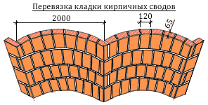
The number of bricks in the arch and rows in the vault should be odd.

The middle upper odd brick is a castle brick.
Arches, designed to cover openings with a width of 2 to 4 m, can have a very different radius of curvature or a different lifting boom.
For brick arch It is typical to use a special masonry method - beam lintel. This design involves erecting the wall to the level of the future lintel, then proceeding to build the arch.

Thickness brickwork in this case there must be at least 1 brick and, as a rule, they are laid out in two layers of equal thickness, and both layers should be made and “locked” in the upper part at the same time.
Circles are made from boards 40 mm thick.
First, circles are made from boards, cut along the contour of the arch. Circles consist of individual jambs, knocked down in two layers with joints spaced apart. The lower part of the circles is connected with boards and on top of the circles a formwork made of planed boards is sewn with nails, which is sheathed with roofing iron, fiberboard, etc.

d. The masonry is laid along the resulting surface, which repeats the shape of the arched lintel. There are also industrial ready-made arched openings that are supplied disassembled.
Along the edges of the span, side supports are installed on which the template is installed and wedges are used to level it horizontally. A cord is pulled between two boards attached to the wall, allowing you to adjust the position of the bricks laid in the direction of the castle.
A wedge-shaped stone or brick is used, which is laid strictly towards the center. In the absence of ready-made pattern bricks, regular solid bricks are hewn, giving it a wedge-shaped shape. When laying arches, you should strictly monitor the quality of the brick, the direction and thickness of the seams, which should not be more than permissible according to the project.

Arches laid out of ordinary brick are made with wedge-shaped seams with a thickness of at least 5 mm at the bottom and no more than 25 mm at the top.
To accurately mark the distance between bricks and the position of the seams, place a brick in the middle of the template, adjust the compass to the thickness of the brick plus 5 mm for the seam filled with mortar, and, starting from the middle brick, measure the distances along the edge of the template to the last full brick. The width of the remaining gap is divided by the resulting number of bricks and the legs of the compass are further adjusted to the final value.
The masonry of the arches is carried out simultaneously from both sides of the heels to the top with careful bandaging of the seams.

The bricks are laid “on edge” in transverse rows according to the formwork template. The radial position of the seam is controlled by a square template. To properly fix the bricks in the masonry, the mortar is spread over the brick bed in a “wedge shape” (with thickening upwards).
The position of the bricks is checked using a cord fixed at one end in the center of the semicircle.
Thickening of seams opposite to those indicated is allowed only in cases provided for by the project.

The seams must be completely filled with mortar. The mason also monitors the front surface of the masonry - the binding pattern, the quality of the brick, its color and shade.
To ensure uniform stress in large arches, it is necessary to build them so quickly that the solution does not have time to completely harden in all parts of the arches before the circle weakens. Solutions should be used on Portland cement.
Deviations in the thickness of joints in masonry should not exceed: - horizontal…………………………………………………………………………. -2; +3 mm

– vertical……………………………………………………………………………….. -2; +2 mm
Main types of vaults

1 – box; 2 – quarter-cylindrical; 3 – dome; 4 – domed with sails without a drum; 5 – dome on the drum; 6 – conha; 7 – gable; 8 – cross; 9 – tent; 10 – 12 – stepped-arched; 13 – unbroken cross; 14, 15 – closed on formworks converging to the corner; 16, 17 – vaulted ceiling on formwork converging to the corner; 18 – closed on formwork, receding from the corner; 19 – closed with free arrangement of formwork; 20 – closed on a faceted base (“faceted dome”); 21 – sailing; 22 – dome on tromps; 23 – cross-shaped with horizontal strips of formwork; 24 – cross-shaped with inclined formwork shells; 25 – cross-shaped with stepped formwork; 26 – closed without formwork; 27 and 28 – semi-tray and tray; 29 – vaulted ceiling of formwork; 30 – tray on formwork; 31 and 32 - variants of the illuminated five-domed pillarless temple
In brick churches, the vaults are laid out on formwork resting on circles and walls or on girth arches lowered in relation to them. After the solution hardens, the circles are removed and the formwork is removed.
You are not authorized to post comments.

Architects often use architectural and design elements in their work that give the building originality and beauty. One of these decorative details is the arch.
Internal structures are easily decorated using plasterboard. Brick is used to construct external geometric elements. Many novice craftsmen are interested in the question: how to make a brick arch with your own hands?
Arches in architecture are used in architecture different nations. Accordingly, their shape was influenced by the cultural heritage of the countries. An example of this is the Arabian arch, widespread in the architecture of Middle Eastern states.

The most common types of arches are:
semicircular or semicircular: has the appearance of a semicircle, the center of which is at the same level as the heels of the arch.
This design is most often supported by pylons. This type arches can be classified as classics; arched: in shape it is an arc equal to a quarter of a circle. Arches of this type adorned the window openings of residential buildings in Ancient Rome; a pointed or broken arch formed by two arches intersecting at an angle.
 types of round arches
IN modern architecture The first two types are used as a decorative element - semicircular (they are now called full) and arched. Wedge arches are no less popular - they received this name thanks to the construction technology: bricks are laid out with a wedge and then secured with a “lock.”
General technology for laying brick arches
Laying a brick arch, regardless of the type chosen, is done in the following order:
- Under development general form arch. Its parameters are calculated. A working drawing is drawn indicating all the required dimensions. A template is made, which is then installed in the opening. The opening lintels are laid out. The brickwork is fixed and fixed. The template is dismantled.
At the last stage, the formed opening is finished.
Template calculation
Before making a brick arch, you need to make an auxiliary structure - a template.
Its quality has a direct impact on the final result. For this reason, it is necessary to carefully calculate its dimensions. As an example, we can consider the design of a window with a width of 1500 mm using a beam type.
Please note: for designing an arched opening, it is not its width that is important, but the length of the arc along which the brick will be laid. In order not to create problems for yourself in the future, you need to adjust this size at the calculation stage so that it is a multiple of 70-75 mm.

The width of the template should be 5 mm less than the opening. This small gap will make it easier to install and disassemble (even if it gets damp).
The height of the auxiliary structure must coincide with the same parameter of the arch. By the way, it should not be too low - this is fraught with subsidence of the brickwork under the influence of load.
Now it remains to decide on the thickness of the template. If it is too large, the weight of the structure will complicate the work. In our example, the optimal thickness can be considered 200 mm.
Making a template
We begin the work by marking the arch on a sheet of chipboard. To do this you need:
- mark the center line; draw the boundaries of the opening symmetrically to the centerline; mark the upper point of the arch on the axis; from the highest point, set down a size equal to the height of the arch, and draw a straight line through the resulting mark, perpendicular to the axis. Mark the intersections of the auxiliary line with the right and left boundaries of the opening with dots; from the same (highest) point, set down a segment equal to the radius of the arched arc - this way the center of the circle is located; install a metal rod (peg) at the central point and tie a piece of knitting to it wire, equal in length to the radius of the circle; attach a pencil to the second end, and using an improvised compass, connect the three previously marked points.
The template consists of two such parts - circles - connected to each other by bars. If the circles are cut exactly according to the markings, then the sharp corners will not make it possible to fasten them to each other. Therefore, before you start cutting, you need to move 100 mm down from the lower points of the arched profile, thus increasing the body of the part.
After this, you can cut out the part with a jigsaw.

Marking the second circle is much easier: to do this, you need to use an already cut piece as a pattern. Just lay it on a new sheet of chipboard and trace along the outline.
The bars intended for fastening the circles must correspond in length to the specified thickness of the template. Twist the prepared parts with self-tapping screws. A strip of fiberboard is nailed along the top of the template - in this way, all possible irregularities in the device are smoothed out.
Circling in window opening for laying a brick arch
Installing the template in the opening
Supports made from edged boards 20 mm thick are installed under the edges of the template. To prevent them from falling, a spacer is inserted between them.

The template is installed on top of supports flush with the edge of the shaped face brick. One nuance should be kept in mind: an arch that is too protruding (more than 60 mm) will be destroyed by frost and rain during operation. If you still decide to take this step, close it from above ceramic tiles or metal.
Laying a brick arch with your own hands
First, lay out the right and left heels of the arch.
After this, you can begin marking the order. This is done using a tape measure. For convenience, markings are made on the template every five bricks.

The decision regarding the thickness of the seam is made on site.
After this, you can lay out an arch from the heels to the highest point - on both sides.
The last one or two bricks (depending on whether the number was even or odd when marking) are called castle bricks. After they are put in place, the seams are carefully filled with mortar. If this is not done, the arch may “sit down”.

The arch - front and backing - must be laid out in one go.
The template can be removed two to three hours after the masonry is crimped. If it is not possible to remove the auxiliary structure on the same day, protect it from possible rain with plastic wrap. Otherwise, the swollen tree may undermine the fresh masonry, and the work will have to be completely redone.
A beautiful brick window or door arch will decorate any interior room.

The masonry technology is simple, but still requires certain skills. Therefore, it is better for the arched opening to be designed and covered by a master. However, if you carefully study the instructions and take into account everything important nuances, draw up a project, then you can lay out the arch in a semicircle with your own hands.
Types of brick arches
The brick arch is decorative element, so it is often used to decorate openings in residential premises. But before you build beautiful arched openings in houses and apartments, it is useful to study information about what types of arches exist. The most common varieties are:
Wedge-shaped. Lovers of Gothic style interiors often resort to the wedge shape.

In this case, the bricklaying should form a wedge arched vault, the upper point of the tip is fixed with a special building element. Romance. In this situation, the opening needs to be laid out rectangular shape, and the corner part is semicircular. Onion. An admirer of oriental-themed interiors can make this type of arch in their own home.
In this case, the bricks are laid in such a way that a vault is formed in the shape of a truncated cone. Classic. This semicircular arch can be framed with decorative pillars if desired. In order for the design to look harmonious, it is important to adjust the size of the semicircle to ½ the width of the main opening.Modern.
Externally, the opening looks like an arc. Porta. A simple design, laid out in the shape of a rectangle. Ellipse. Such an arch is round on the arch and can have different widths.
Return to contents
Advantages and disadvantages
Despite the fact that semicircular arched window and door ceilings are considered an interesting interior solution, they have their pros and cons, which are important to consider before starting construction.
This decor is used for window openings.
The main advantages of such structures are as follows:
Unique atmosphere in the house.
The vaults of the entrance or interior door create a special, pleasant atmosphere that will be felt by the owners of the room and their guests. Simple design and installation. Even without construction experience, after carefully studying the construction diagram, you will be able to build a red brick door arch in your house yourself. Reliability of the structure. The arch represents monolithic structure, capable of withstanding increased loads. Versatility.

You can fold an arch not only inside the house. It is often used to frame entrance gates, gates, and window openings. Even the hole in the stove can be lined with brick in the shape of an arched arc, which is also original solution and a beautiful addition to the overall interior of the room.
However, this structure also has disadvantages, for example:
- A semicircular arch requires the creation of a unified interior style, which includes specific cladding of walls, windows, and floors. The implementation of these ideas will require significant expenditures of labor, materials and finances, which not everyone can afford. Strict, step-by-step adherence to masonry technology. If you incorrectly calculate the dimensions or form a brick vault not according to the design, there is a high risk that the structure will not hold up and will fall apart.