Clone PI-W and, now, it came to making a mono search coil. And since I am currently experiencing some financial difficulties, I was faced with a difficult task - to make a reel myself from the cheapest materials possible.
Looking ahead, I’ll say right away that I coped with the task. As a result, I got this sensor:
By the way, the resulting ring coil is perfect not only for Clone, but also for almost any other impulse generator (Koschei, Tracker, Pirate).
I will tell you in great detail, since the devil is often in the details. Moreover, there are a dime a dozen short stories about making reels on the internet (like, take this, then cut it off, wrap it, glue it and you’re done!) But you start doing it yourself and it turns out that the most important things were mentioned in passing, and some things were completely forgotten to say ... And it turns out that everything is more complicated than it seemed at the very beginning.
This won't happen here. Ready? Go!
Idea
Easiest for self-made This design seemed to me: we take a disk made of sheet material ~4-6 mm thick. The diameter of this disk is determined by the diameter of the future winding (in my case it should be 21 cm).
Then we glue two disks of slightly larger diameter to this pancake on both sides to make a bobbin for winding wire. Those. such a coil greatly increased in diameter, but flattened in height.
For clarity, I’ll try to depict this in a drawing: 
I hope the main idea is clear. Just three disks glued together over the entire area.
Material selection
I planned to use plexiglass as the material. It is perfectly processed and glued with dichloroethane. But, unfortunately, I couldn’t find it for free.
All sorts of collective farm materials such as plywood, cardboard, bucket lids, etc. I immediately discarded them as unsuitable. I wanted something strong, durable and preferably waterproof.
And then my gaze turned to fiberglass...
It's no secret that fiberglass (or glass mat, fiberglass) is used to make whatever your heart desires. Even motor boats and car bumpers. The fabric is impregnated with epoxy resin, given the desired shape and left until completely cured. The result is a durable, water-resistant, easy-to-handle material. And this is exactly what we need.
So, we need to make three pancakes and ears for attaching the barbell.
Manufacturing of individual parts
Pancakes No. 1 and No. 2
Calculations showed that to obtain a sheet 5.5 mm thick, you need to take 18 layers of fiberglass. To reduce epoxy consumption, it is better to pre-cut the fiberglass into circles of the required diameter.
For a disk with a diameter of 21 cm, 100 ml of epoxy resin was just enough.
Each layer must be thoroughly coated, and then the entire stack must be placed under the press. The greater the pressure, the better - the excess resin will be squeezed out, the mass of the final product will become a little less, and the strength will be a little greater. I loaded about a hundred kilograms on top and left it until the morning. The next day I ended up with this pancake: 
This is the most massive part of the future coil. He weighs - be healthy! 
Then I’ll tell you how using this spare part it will be possible to significantly reduce the weight of the finished sensor.
A disk with a diameter of 23 cm and a thickness of 1.5 mm was made in exactly the same way. Its weight is 89 g.
Pancake #3
There was no need to glue the third disk. I had a sheet of fiberglass at my disposal. suitable size and thickness. It was printed circuit board from some ancient device: 
Unfortunately, the board had metallized holes, so I had to spend some time drilling them.
I decided that this would be the top disk, so I made a hole in it for the cable entry. 
Ears for barbell
There was just enough leftover textolite for the ears to attach the sensor housing to the rod. I cut out two pieces for each ear (to make it durable!) 
You should immediately drill holes in your ears for the plastic bolt, as it will be very inconvenient to do this later. 
By the way, this is a mounting bolt for the toilet seat.
So, all the components of our coil are ready. All that remains is to glue it all together into one big sandwich. And don't forget to run the cable inside.
Assembly into one piece
First, the upper disk made of holey fiberglass was glued to the middle pancake made of 18 layers of fiberglass. This took literally a few milliliters of epoxy - this was enough to coat both surfaces to be glued over the entire area. 


Ear mounting
I cut the grooves using a jigsaw. Naturally, I overdid it a little in one place: 
To make the ears fit well, I made a small bevel on the edges of the cuts: 
Now we had to decide which option is better? Ears can be placed in different ways... 
Reels industrial production Most often they are made according to the right version, but I like the left one better. In general, I often make leftist decisions...
In theory, the right method is better balanced, because The rod mount is closer to the center of gravity. But it is far from a fact that after lightening the coil, its center of gravity will not shift in one direction or another.
The left mounting method looks more visually pleasing (IMHO), and in this case the total length of the metal detector when folded will be a couple of centimeters shorter. For someone who plans to carry the device in a backpack, this may be important.
In general, I made my choice and started gluing. He generously smeared it with bauxite, securely fixed it in the desired position and left it to harden: 
After hardening, everything sticking out from reverse side sanded it off with sandpaper: 

Cable entry
Then, using a round file, I prepared grooves for the conductors, inserted the connecting cable through the hole and glued it tightly: 

To prevent strong kinks, the cable at the entry point needed to be somehow reinforced. For these purposes, I used this little rubber thing that I got from God knows where: 
All that remained was to glue the third pancake (the bottom).
Finishing the frame
To glue the third pancake it took several milliliters of bauxite and a couple of hours for everything to set. Here's the result:  Thus, I received a rigid and durable frame, fully prepared for winding the wire.
Winding sealing
An enameled copper wire with a diameter of 0.71 mm was used as a winding wire. After winding 27 turns, the sensor became heavier by another 65 grams: 
Now the winding had to be caulked somehow. As a putty I used a mixture of epoxy resin and finely chopped fiberglass (I learned about this super recipe from).
In short, I cut some fiberglass: 
and mixed it thoroughly with bauxite with the addition of paste from ballpoint pen. The result was a viscous substance similar to wet hair. With this composition you can cover any cracks without problems: 
Pieces of fiberglass give the putty the necessary viscosity, and after hardening, provide increased strength to the adhesive joint.
So that the mixture is properly compacted, and the resin saturates the turns of the wire, I wrap it all with electrical tape tightly: 
The electrical tape must be green or, at worst, blue.
After everything froze thoroughly, I wondered how strong the structure turned out to be. It turned out that the reel could easily support my weight (about 80 kg).
In fact, we don’t need such a heavy-duty reel; its weight is much more important. Too much large mass the sensor will definitely make itself felt by pain in the shoulder, especially if you plan to conduct a long search.
Facilitating
To reduce the weight of the coil, it was decided to cut out some sections of the structure: 
This manipulation allowed me to lose 168 grams excess weight. At the same time, the strength of the sensor has practically not decreased, as can be seen in this video:
Now, with hindsight, I understand how the coil could have been made a little lighter. To do this, it was necessary to make large holes in the middle pancake in advance (before gluing everything together). Something like this: 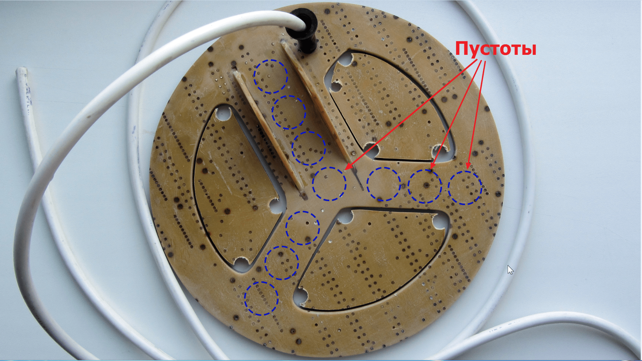
The voids inside the structure would have almost no effect on the strength, but would reduce the total mass by another 20-30 grams. Now, of course, it’s too late to rush around, but I’ll keep it in mind for the future.
Another way to simplify the design of the sensor is to reduce the width of the outer ring (where the wire turns are laid) by 6-7 millimeters. Of course, this can be done now, but there is no such need yet.
Finish painting
I found an excellent paint for fiberglass and fiberglass products - epoxy resin with the addition of dye desired color. Since the entire structure of my sensor is made on the basis of bauxite, the resin-based paint will have excellent adhesion and will fit like original.
Used as a black dye alkyd enamel PF-115, adding it until the desired coverage is obtained.
As practice has shown, a layer of such paint holds very firmly, and looks as if the product was dipped in liquid plastic: 

In this case, the color can be any depending on the enamel used.
The final weight of the search coil together with the cable after painting is 407 g 
The cable separately weighs ~80 grams.
Examination
After our homemade metal detector coil was completely ready, we had to check it for internal breaks. The easiest way to check is to use a tester to measure the winding resistance, which normally should be very low (maximum 2.5 Ohms).
In my case, the resistance of the coil together with two meters of connecting cable turned out to be around 0.9 Ohm.
Unfortunately, this in a simple way It will not be possible to detect an interturn short circuit, so you have to rely on your accuracy when winding. A short circuit, if there is one, will immediately manifest itself after starting the circuit - the metal detector will consume increased current and have extremely low sensitivity.
Conclusion
So, I think that the task was completed successfully: I managed to make a very durable, waterproof and not too heavy reel from the most waste materials. List of expenses:
- Fiberglass sheet 27 x 25 cm - free;
- Sheet of fiberglass, 2 x 0.7 m - free;
- Epoxy resin, 200 g - 120 rubles;
- Enamel PF-115, black, 0.4 kg - 72 RUR;
- Winding wire PETV-2 0.71 mm, 100 g - 250 rub;
- Connecting cable PVS 2x1.5 (2 meters) - 46 rubles;
- Cable entry is free.
Now I am faced with the task of making exactly the same rogue barbell. But that's already it.
The famous inventor Nikola Tesla has many merits to science and technology, but only one invention bears his name. This is a resonant transformer, also known as a Tesla coil.
A Tesla transformer consists of a primary and secondary winding, a circuit that provides power to the primary winding at the resonant frequency of the secondary, and optionally additional capacitance at the high-voltage output of the secondary winding. The tip, mounted on an additional container, increases the electric field strength, facilitating air breakdown. The additional capacitance reduces the operating frequency, reducing the load on the transistors, and, according to some data, increases the length of the discharges. A piece of sewer PVC pipe is used as the frame of the secondary winding. The secondary winding consists of approximately 810 turns of enameled wire with a diameter of 0.45 mm. The primary winding consists of eight turns of wire with a cross section of 6 mm2. The power circuit is based on the principle of self-oscillation and is built on power transistors.
The essence of Tesla's invention is simple. If a transformer is fed with a current at a frequency equal to the resonant frequency for its secondary winding, the output voltage increases tens and even hundreds of times. In fact, it is limited by the electrical strength of the surrounding air (or other medium) and the transformer itself, as well as losses due to radio wave radiation. The reel is most famous in the field of show business: it is capable of throwing lightning bolts!
Form and content
The transformer looks very unusual - it seems like it was specially designed for show business. Instead of the usual massive iron core with thick windings, there is a long hollow tube made of dielectric, on which the wire is wound in just one layer. This strange appearance is caused by the need to ensure maximum electrical strength of the structure.
Apart from the unusual appearance, the Tesla transformer has one more feature: it necessarily has a certain system that creates a current in the primary winding precisely at the resonant frequency of the secondary. Tesla himself used the so-called spark circuit (SGTC, Spark Gap Tesla Coil). Its principle is to charge the capacitor from a power source and then connect it to the primary winding. Together they create an oscillatory circuit.
The capacitance of the capacitor and the inductance of the winding are selected so that the oscillation frequency in this circuit coincides with the required one. Switching is carried out using a spark gap: as soon as the voltage on the capacitor reaches a certain value, a spark appears in the gap, closing the circuit. You can often see statements that “the spark contains a full spectrum of frequencies, so there is always a resonant one there, which is how the transformer works.” But this is not so - without correct selection capacitance and inductance cannot produce a truly high output voltage.
Having decided to make our own Tesla transformer, we settled on a more progressive circuit - a transistor one. Transistor generators potentially allow you to obtain any signal shape and frequency in the primary winding.
The circuit we have chosen consists of a power transistor driver microcircuit, a small transformer to isolate this driver from the 220 V supply voltage, and a half-bridge of two power transistors and two film capacitors. The transformer is wound on a ferrite ring with an operating frequency of at least 500 kHz; three windings of 10-15 turns of wire are made on it. It is very important to connect the transistors to the windings of the transformer so that they operate in antiphase: when one is open, the other is closed.
The required frequency occurs due to feedback with a secondary winding (the circuit is based on self-oscillations). Feedback can be carried out in two ways: using either a current transformer of 50-80 turns of wire on the same ferrite ring as the isolation transformer, through which the ground wire of the lower part of the secondary winding passes, or... just a piece of wire that acts as an antenna, catching radio waves emitted by the secondary winding.
Let's go crazy
As the frame of the primary winding we took sewer pipe made of PVC with a diameter of 9 cm and a length of 50 cm. For winding we use enameled copper wire with a diameter of 0.45 mm. We place the frame and coil of winding wire on two parallel axes. The axis of the frame was a piece of PVC pipe with a smaller diameter, and the role of the axis of the coil with the wire was played by a bow arrow lying around in the editorial office.
There are three primary winding options: flat helix, short helical and tapered winding. The first provides maximum electrical strength, but at the expense of inductive coupling strength. The second, on the contrary, creates the best connection, but the higher it is, the greater the chance that a breakdown will occur between it and the secondary winding. Tapered winding is an intermediate option that provides the best balance between inductive coupling and dielectric strength. We didn’t expect to achieve record voltages, so the choice fell on a screw winding: it allows us to achieve maximum efficiency and easy to make.
As a conductor, we took an audio equipment power cable with a cross-section of 6 mm², eight turns of which were wound onto a piece of PVC pipe of a larger diameter than that of the secondary winding frame, and secured with ordinary electrical tape. This option cannot be considered ideal, because high-frequency current flows only along the surface of the conductors (skin effect), so it is more correct to make the primary winding from a copper pipe. But our method is easy to manufacture and works quite well if the power is not too high.
Control
For feedback, we initially planned to use a current transformer. But it turned out to be ineffective at low coil powers. And in the case of an antenna, it is more difficult to provide the initial impulse that will start the oscillations (in the case of a transformer, another wire can be passed through its ring, to which a regular battery can be short-circuited for a split second). As a result, we ended up with a mixed system: one output of the transformer was connected to the input of the microcircuit, and the wire of the second was not connected to anything and served as an antenna.
Short circuits, breakdown of transistors and other troubles were initially assumed to be very possible, so an additional control panel was made with a 10 A AC ammeter, a 10 A automatic fuse and a pair of “neons”: one shows whether there is voltage at the input to the remote control, and the other is whether current flows to the coil. Such a remote control allows you to conveniently turn the coil on and off, monitor the main parameters, and also makes it possible to significantly reduce the frequency of trips to the control panel to turn on “knocked out” machines.
The last optional part of the transformer is an additional capacitance in the form of a conducting ball or torus at the high-voltage output of the secondary winding. In many articles you can read that it can significantly lengthen the discharge (by the way, this is a wide field for experiments). We made such a 7 pF capacitance by putting together two steel hemispherical cups (from IKEA).
Assembly
Once all components are fabricated, final assembly of the transformer is a breeze. The only subtlety is grounding the lower end of the secondary winding. Alas, not all domestic houses have sockets with separate ground contacts. And where there are, these contacts are not always actually connected (you can check this with a multimeter: there should be about 220 V between the contact and the phase wire, and almost zero between it and the neutral wire).
If you have such sockets (we found them in our editorial office), then you need to ground them with their help, using the appropriate plug to connect the coil. It is often recommended to ground the battery central heating, but this is strictly not recommended, since in some cases it can lead to the fact that the batteries in the house will shock unsuspecting neighbors.
But then comes the crucial moment of switching on... And immediately the first victim of lightning appears - the transistor of the power circuit. After replacement, it turns out that the circuit is, in principle, quite functional, albeit at low powers (200-500 W). When reaching the design power (about 1-2 kW), the transistors explode with a spectacular flash. And although these explosions do not pose a danger, the “one second of operation - 15 minutes of transistor replacement” mode is not satisfactory. Nevertheless, with the help of this transformer you can quite feel yourself in the role of Zeus the Thunderer.
Noble goals
Although today the Tesla transformer, at least in its original form, is most often used in a variety of shows, Nikola Tesla himself created it for much more important purposes. A transformer is a powerful source of radio waves with a frequency from hundreds of kilohertz to several megahertz. Based on Tesla's powerful transformers, it was planned to create a radio broadcasting system, wireless telegraph and wireless telephony.
But Tesla's most ambitious project involving the use of his transformer is the creation of a global wireless power supply system. He believed that a sufficiently powerful transformer or system of transformers would be able to change the charge of the Earth and the upper layers of the atmosphere on a global scale.
In such a situation, a transformer installed anywhere on the planet, having the same resonant frequency as the transmitting one, will be a source of current, and power lines will no longer be needed.
It was the desire to create a wireless power transmission system that ruined the famous Wardenclyff project. Investors were interested in the appearance of only a communication system that would pay off. And the transmitter of energy, which could be uncontrolledly received by anyone around the world, on the contrary, threatened electric companies and wire manufacturers with losses. And one of the main investors was a shareholder of the Niagara hydroelectric power station and copper production plants...
In this article I will talk about the Tesla transformer device I assembled and about interesting effects, which were observed in him during his work.
I immediately want to dot the i’s, this device works with high voltages, therefore, compliance with basic safety rules is MANDATORY! Failure to follow the rules will result in serious injury, remember this! I would also like to note that the main danger in this device is the ISKROVIK (arrester), which during its operation is a source of radiation wide range including X-ray, remember this!
Let's begin. I’ll tell you briefly about the design of “my” Tesla transformer, in common parlance “Tesla coil”. This device is made on a simple element base, accessible to everyone. The block diagram of the device is shown below.
As you can see, I did not reinvent the wheel and decided to stick to the classic Tesla transformer circuit, the only thing added to the classic circuit is an electronic voltage converter - the role of which is to increase the voltage from 12 Volts to 10 thousand volts! By the way, this voltage converter can be assembled by a housewife. In the high-voltage part of the circuit, the following elements are used: The VD diode is a high-voltage 5GE200AF diode - it has high resistance - this is very important! Capacitors C1 and C2 have a nominal value of 2200 pF, each designed for a voltage of 5 kV. As a result, we get a total capacitance of 1100 pF and an accumulated voltage of 10 kV, which is very good for us! I would like to note that the capacitance is selected experimentally; the duration of the pulse in the primary coil depends on it, and of course on the coil itself. The pulse time must be less than the lifetime of electron pairs in the conductor of the primary coil of the Tesla transformer, otherwise we will have a low effect and the pulse energy will be spent on heating the coil - which we do not need! The assembled design of the device is shown below.
The design of the spark gap deserves special attention; most modern Tesla transformer circuits have a special spark generator design driven by an electric motor, where the discharge frequency is regulated by the rotation speed, but I decided not to follow this trend, since there are many negative aspects. I followed the classic arrester circuit. The technical drawing of the arrester is given below.
Cheap and practical option It doesn’t make noise or light up, I’ll explain why. This arrester is made of copper plates 2-3 mm thick with dimensions 30x30 mm (to act as a radiator, since the arc is a heat source) with threads for bolts in each plate. To prevent the bolt from unwinding during discharge and to ensure good contact, it is necessary to use a spring between the bolt and the plate. To dampen the noise during a discharge, we will make a special chamber where the arc will burn, my chamber is made from a piece of polyethylene water pipe (which does not contain reinforcement), the piece of pipe is clamped tightly between two plates and it is advisable to use sealing, for example, I have a special double-sided tape for insulation . The gap is adjusted by screwing in and unscrewing the bolt; I’ll explain why later.
Primary coil of the device. The primary coil of the device is made of copper wire type PV 2.5mm.kv and here the question arises: “Why such a thick wire?” I'll explain. The Tesla transformer is a special device, one might say anomalous, which is not of the same type as ordinary transformers, where the laws are completely different. For a conventional power transformer, self-induction (counter-EMF) is important in its operation, which compensates for part of the current; when a conventional power transformer is loaded, the counter-EMF decreases and the current increases accordingly; if we remove the counter-EMF from conventional transformers, they will flare up like candles. But in the Tesla transformer it’s the other way around - self-induction is our enemy! Therefore, to combat this disease, we use a thick wire that has low inductance, and therefore low self-inductance. We need a powerful electromagnetic pulse and we get it using this type of coil. The primary coil is made in the form of an Archimedes spiral in one plane in the amount of 6 turns, the maximum diameter of a large turn in my design is 60 mm.
The secondary coil of the device is a regular coil wound on a polymer water pipe(without reinforcement) with a diameter of 15 mm. The coil is wound with enamel wire 0.01mm.kv turn per turn, in my device the number of turns is 980 pcs. Winding the secondary coil requires patience and endurance, it took me about 4 hours.
So, the device is assembled! Now a little about adjusting the device, the device consists of two LC circuits - primary and secondary! For proper operation devices - it is necessary to introduce the system into resonance, namely into resonance of the LC circuits. In fact, the system is brought into resonance automatically, due to the wide range of frequencies electric arc, some of which coincide with the impedance of the system, so all we have to do is optimize the arc and equalize the frequencies in terms of power in it - this is done very simply - we adjust the gap of the arrester. The arrester must be adjusted until best results in the form of arc length. An image of the working device is located below.
So the device was assembled and launched - now it works for us! Now we can make our observations and study them. I want to warn you right away: although high-frequency currents are harmless to the human body (in terms of the Tesla transformer), but lighting effects caused by them can affect the cornea of the eye and you risk getting a corneal burn, since the spectrum of the emitted light is shifted towards ultraviolet radiation. Another danger that lurks when using a Tesla transformer is an excess of ozone in the blood, which can lead to headaches, since large portions of this gas are produced during operation of the device, remember this!
Let's start observing a working Tesla coil. It is best to make observations in complete darkness, so you will most of all experience the beauty of all the effects that will simply amaze you with their unusualness and mystery. I made observations in complete darkness, at night and for hours I could admire the glow that the device produced, for which I paid the price the next morning: my eyes hurt like after a burn from electric welding, but these are trifles, as they say: “science requires sacrifices.” As soon as I turned on the device for the first time, I noticed a beautiful phenomenon - this is a glowing purple ball that was in the middle of the coil, in the process of adjusting the spark gap, I noticed that the ball moves up or down depending on the length of the gap, my only explanation for the phenomenon at the moment impedance in the secondary coil, which causes this effect. The ball consisted of many purple micro arcs that exited one area of the coil and entered another, forming a sphere. Since the secondary coil of the device is not grounded, an interesting effect was observed - purple glows at both ends of the coil. I decided to check how the device behaves with the secondary coil closed and noticed another interesting thing: intensification of the glow and increase in the arc coming from the coil while touching it - an amplification effect on the face. A repetition of Tesla's experiment, in which gas-discharge lamps glow in the field of a transformer. When a conventional energy-saving gas-discharge lamp is inserted into the transformer field, it begins to glow, the brightness of the glow is approximately 45% of its full power, which is approximately 8 W, while the power consumption of the entire system is 6 W. Note: high-frequency noise occurs around the operating device. electric field which has a potential of approximately 4 kV/cm2. An interesting effect is also observed: the so-called brush discharge, a luminous purple discharge in the form of a thick brush with frequent needles up to 20 mm in size, reminiscent of an animal’s fluffy tail. This effect is caused by high-frequency vibrations of gas molecules in the field of a conductor; in the process of high-frequency vibrations, gas molecules are destroyed and ozone is formed, and the residual energy manifests itself in the form of a glow in the ultraviolet range. The most striking manifestation of the brush effect occurs when using a flask with an inert gas, in my case I used a flask from a HPS gas discharge lamp, which contains Sodium (Na) in a gaseous state, and a bright brush effect occurs, which is similar to the burning of a wick only with very frequent formation of sparks, this effect is very beautiful.
Results of the work carried out: The operation of the device is accompanied by various interesting and beautiful effects, which in turn deserve more careful study; it is known that the device generates a high-frequency electric field, which causes the formation large quantity ozone as a by-product of ultraviolet glow. The special configuration of the device gives reason to think about the principles of its operation; there are only guesses and theories about the operation of this device, but no objective information has been put forward, just as there has been no thorough study of this device. At the moment, the Tesla transformer is collected by enthusiasts and used only for entertainment for the most part, although the device in my opinion is the key to understanding the fundamental basis of the universe that Tesla knew and understood. Using a Tesla transformer for fun is like hammering nails with a microscope... Super single effect of the device..? perhaps..., but I don’t yet have the necessary equipment to determine this fact.
The idea of generating “fuel-free” electricity at home is extremely interesting. Any mention of current technology instantly attracts the attention of people who want to receive the intoxicating possibilities of energy independence free of charge. To draw correct conclusions on this topic, it is necessary to study theory and practice.
The generator can be assembled without much difficulty in any garage
How to create a perpetual generator
The first thing that comes to mind when mentioning such devices is the inventions of Tesla. This person cannot be called a dreamer. On the contrary, he is known for his projects that were successfully implemented in practice:
- He created the first transformers and generators operating on high-frequency currents. In fact, he founded the corresponding direction of electrical RF equipment. Some of the results of his experiments are still used in safety regulations.
- Tesla created a theory on the basis of which designs appeared electric machines multiphase type. Many modern electric motors are based on his developments.
- Many researchers rightly believe that Tesla also invented the transmission of information over a distance using radio waves.
- His ideas were implemented in the patents of the famous Edison, according to historians.
- The giant towers, power generators that Tesla built, were used for many experiments that were fantastic even by modern standards. They created an aurora at the latitude of New York and caused vibrations comparable in strength to powerful natural earthquakes.
- The Tunguska meteorite, they say, was in fact the result of an experiment by the inventor.
- The small black box that Tesla installed in a production car with an electric motor provided full power for many hours without batteries or wires.

Experiments in the Tunguska region
Only some of the inventions are listed here. But even brief descriptions Some of them suggest that Tesla created a “perpetual” motion machine with his own hands. However, the inventor himself used not spells and miracles for calculations, but quite materialistic formulas. It should be noted, however, that they described a theory of the ether, which is not recognized by modern science.
To check in practice you can use standard schemes devices.
If you use an oscilloscope to measure the oscillations that a “classical” Tesla coil produces, interesting conclusions will be drawn.

Voltage oscillograms at different types inductive coupling
Strong inductive coupling is ensured in a standard way. To do this, a core made of transformer iron or other suitable material is installed in the frame. The right side of the figure shows the corresponding vibrations and the results of measurements on the primary and secondary coils. The correlation of processes is clearly visible.
Now you need to pay attention to the left side of the picture. After applying a short-term pulse to the primary winding, the oscillations gradually die out. However, a different process was recorded on the second coil. The oscillations here have a clearly expressed inertial nature. They do not fade out for some time without external replenishment of energy. Tesla believed that this effect explains the presence of ether, a medium with unique properties.
The following situations are cited as direct evidence of this theory:
- Self-charging of capacitors not connected to an energy source.
- A significant change in the normal parameters of power plants, which is caused by reactive power.
- The appearance of corona discharges on a coil that is not connected to the network, when it is placed at a great distance from a working similar device.
The last of the processes occurs without additional energy expenditure, so we should consider it more carefully. Below is circuit diagram Tesla coils, which can be assembled without much difficulty with your own hands at home.

Schematic diagram of Tesla coils
The following list shows the main product parameters and features that must be taken into account during the installation process:
- For a large primary winding design, you will need a copper tube with a diameter of about 8 mm. This coil consists of 7-9 turns, laid with a spiral expansion towards the top.
- The secondary winding can be made on a frame made of a polymer pipe (diameter from 90 to 110 mm). PTFE works well. This material has excellent insulating characteristics and maintains the integrity of the product structure over a wide temperature range. The conductor is selected to make 900-1100 turns.
- A third winding is placed inside the pipe. To assemble it correctly, use a stranded wire in a thick sheath. The cross-sectional area of the conductor should be 15-20 mm 2. The amount of voltage at the output will depend on the number of turns.
- To fine-tune the resonance, all windings are tuned to the same frequency using capacitors.
Practical implementation of projects
The example given in the previous paragraph describes only part of the device. There is no precise indication of electrical quantities or formulas.
You can make a similar design with your own hands. But you will have to look for circuits of the exciting generator, perform numerous experiments on the relative position of the blocks in space, and select frequencies and resonances.
They say that luck smiled on someone. But in open access it is impossible to find complete data or credible evidence. Therefore, only real products that you can actually make at home yourself will be considered below.
The following figure shows the principle electrical diagram. It is assembled from inexpensive standard parts that can be purchased at any specialized store. Their denominations and designations are indicated in the drawing. Difficulties may arise when searching for a lamp that is not currently commercially available. To replace, you can use 6P369S. But you need to understand that this vacuum device is designed for less power. Since there are few elements, it is permissible to use the simplest wall-mounted installation, without making a special board.

Electrical circuit of the generator
The transformer indicated in the figure is a Tesla coil. It is wound on a dielectric tube, guided by the data from the following table.
Number of turns depending on winding and conductor diameter
The free wires of the high-voltage coil are installed vertically.
To ensure the aesthetics of the design, you can make a special case with your own hands. It will also be useful for securely fixing the block on a flat surface and subsequent experiments.

One of the generator design options
After connecting the device to the network, if everything is done correctly and the elements are in good condition, you will be able to admire the coronary glow.
The three-coil circuit shown in the previous section can be used in conjunction with this device for experiments in order to create a personal source of free electricity.

Coronary radiation over the coil
If it is preferable to work with new components, it is worth considering the following scheme:

Field-effect transistor generator circuit
The main parameters of the elements are shown in the drawing. Explanations for assembly and important additions are listed in the following table.
Explanations and additions to the assembly of a field-effect transistor generator
| Detail | Main settings | Notes |
|---|---|---|
| Field-effect transistor | You can use not only the one marked in the diagram, but also another analogue that works with currents from 2.5-3 A and voltages of more than 450 V. | Before installation operations, it is necessary to check the functional condition of the transistor and other parts. |
| Chokes L3, L4, L5 | It is acceptable to use standard parts from the line scan unit of the TV. | Recommended power – 38 W |
| Diode VD 1 | It is possible to use an analogue. | Rated current of the device is from 5 to 10 A |
| Tesla Coil (Primary Winding) | It is created from 5-6 turns of thick wire. Its strength allows you not to use an additional frame. | The thickness of the copper conductor is from 2 to 3 mm. |
| Tesla Coil (Secondary Winding) | Consists of 900-1100 turns on a tubular base of dielectric material with a diameter of 25 to 35 mm. | This winding is high-voltage, so it will be useful to additionally impregnate it with varnish, or create a protective layer with fluoroplastic film. To create the winding, a copper wire of 0.3 mm in diameter is used. |
Skeptics who deny the very possibility of using “free” energy, as well as those people who do not have basic skills to work with electrical equipment, can make the following installation with their own hands:

Unlimited source of free energy
Let the reader not be confused by the lack of many details, formulas and explanations. Everything ingenious is simple, isn’t it? Here is a schematic diagram of one of Tesla's inventions, which has survived to this day without distortion or correction. This installation generates current from sunlight without special batteries or converters.
The fact is that in the radiation flux of the star closest to Earth there are particles with positive charges. When hitting the surface of a metal plate, a process of charge accumulation occurs in an electrolytic capacitor, which is connected to a standard ground electrode with the negative side. To increase efficiency, the energy receiver is installed as high as possible. Aluminum foil is suitable for baking food in the oven. With your own hands, using available tools, you can make a base for securing it and raise the device to a greater height.
But don't rush to the store. The performance of such a system is minimal (below is a table with information on the device).
Exact experimental data
On a sunny day after 10 o'clock measuring device showed 8 volts at the capacitor terminals. Within a few seconds in this mode, the discharge was completely spent.
Obvious conclusions and important additions
Despite the fact that a simple solution has not yet been presented to the public, it cannot be said that the electromagnetic generator of the great inventor Tesla does not exist. Doesn't accept ether theory modern science. The current systems of economics, production, and politics will be destroyed by free or very cheap energy sources. Of course, there are many opponents of their appearance.

This man was able to create a working generator
Video. DIY generator.
But using the above diagrams, you can assemble working models for experiments with your own hands. It is possible that the manufactured coil will have unique parameters that can change the course of history.
Many of us admire the genius of Nikola Tesla, who made such discoveries back in the 19th century that not all of his scientific heritage has yet been studied and understood. One of his inventions was called the Tesla coil or Tesla transformer. You can read more about it. And here we will look at how to make a simple Tesla coil at home.
What is needed to make a Tesla coil?
To make a Tesla coil at home, at our desk or even in the kitchen, we first need to stock up on everything we need.
So, first we must find or purchase the following.
The tools we need are:
- Soldering iron
- Glue gun
- Drill with thin drill bit
- Hacksaw
- Scissors
- Insulating tape
- Marker
To assemble the Tesla coil itself, you need to prepare the following:
- A piece of thick polypropylene pipe with a diameter of 20 mm.
- Copper wire with a diameter of 0.08-0.3 mm.
- A piece of thick wire
- Transistor type KT31117B or 2N2222A (can be KT805, KT815, KT817)
- Resistor 22 kOhm (you can take resistors from 20 to 60 kOhm)
- Power supply (Krona)
- Ping pong ball
- A piece of food foil
- The base on which the product will be mounted is a piece of board or plastic
- Wires for connecting our circuit
Having prepared everything you need, we begin making the Tesla coil.
Instructions for making a Tesla coil
The most labor-intensive process for making a Tesla coil at home will be winding the secondary winding L2. This is the most significant element in the Tesla transformer. And winding is a labor-intensive process that requires care and attention.
Let's prepare the base. For this purpose, we will use a PVC pipe with a diameter of 2 cm. 
Mark the required length on the pipe - approximately from 9 to 20 cm. It is advisable to maintain a proportion of 4-5:1. Those. if you have a pipe with a diameter of 20 mm, then its length will be from 8 to 10 cm. 
Then we cut off with a hacksaw along the mark left by the marker. The cut must be even and perpendicular to the pipe, since we will then glue this pipe to the board, and a ball will be glued on top. 
The end of the pipe must be sanded with sandpaper on both sides. It is necessary to remove the shavings remaining from sawing off a piece of pipe, and also level the surface for gluing it to the base. 
One hole must be drilled at both ends of the pipe. The diameter of these holes should be such that the wire that we will use when winding can pass through there freely. Those. these should be small holes. If you do not have such a thin drill, you can solder the pipe using a thin nail, heating it on the stove. 
We pass the end of the wire for winding into the pipe. 
We fix this end of the wire with a glue gun. We fix it from the inside of the pipe. 
We begin winding the wire. To do this, you can use copper wire with insulation with a diameter of 0.08 to 0.3 mm. The winding should be tight and neat. Avoid overlaps. The number of turns is from 300 to 1000, depending on your pipe and wire diameter. In our version, 0.08 mm wire is used. diameter and 300 turns of winding. 
After winding is finished, cut the wire, leaving a piece of 10 centimeters. 
Pass the wire through the hole and secure it on the inside with a drop of glue. 
Now you need to glue the manufactured coil to the base. As a base, you can take a small board or a piece of plastic measuring 15-20 cm. To glue the coil, you need to carefully coat its end. 
Then we attach the secondary winding of the coil to its place on the base. 
Then we glue the transistor, switch and resistor to the base. Thus, we fix all the elements on the board. 
We make coil L1. For this we need thick wire. Diameter - from 1 mm. and more, depending on your reel. In our case, the thickness is 1 mm. the wire will be enough. We take the rest of the pipe and wind 3 turns of thick insulated wire around it. 
Then we put the coil L1 on L2. 
We assemble all the elements of the Tesla coil according to this diagram.
 Circuit diagram of a simple Tesla coil
 We attach all elements and wires to the base using a glue gun. We also glue the Krona battery so that nothing dangles. 
Now we have to make the last element of the Tesla transformer - the emitter. It can be made from a tennis ball wrapped in food foil. To do this, take a piece of foil and simply wrap the ball in it. We trim off the excess so that the ball is evenly wrapped in foil and nothing sticks out. 
We attach the ball in the foil to the upper wire of the L2 coil, pushing the wire inside the foil. We secure the attachment point with a piece of electrical tape and glue the ball to the top of L2. 
That's all! We made our own Tesla coil! This is what this device looks like. 
Now all that remains is to check the performance of the Tesla transformer we made. To do this, you need to turn on the device, pick it up fluorescent lamp and bring it to the reel. We must see how the lamp brought to us lights up and burns right in our hands! 
This means that everything worked out and everything works! You have become the owner of a Tesla coil made by yourself. If problems suddenly arise, check the voltage on the battery. Often, if a battery has been lying somewhere for a long time, it no longer works as expected.
But we hope everything worked out for you! You can try changing the number of turns on the secondary winding of coil L2, as well as the number of turns and thickness of the wire on coil L1. The power supply can also vary from 6 to 15 V for such small coils. Try it, experiment! And you will succeed!